What is a transmission electron microscope?
Transmission electron microscopy (TEM) is a technique used to observe features of very small samples. The technique uses a beam of accelerated electrons that passes through very thin samples, allowing scientists to observe features such as structure and morphology.
In 1932, German scientists Max Knoll and Ernst Ruska invented a transmission electron microscope using an electron beam as the light source. The wavelength of the electron beam is much shorter than visible light and ultraviolet light, and the wavelength of the electron beam is inversely proportional to the square root of the voltage of the emitted electron beam. In other words, the higher the voltage, the shorter the wavelength. TEM can see fine structures smaller than 0.2um that cannot be seen clearly under an optical microscope. These structures are called submicroscopic structures or ultrastructure.
Transmission electron microscopy (TEM) has been used as a powerful research method for more than 70 years. Today, transmission electron microscopy (TEM) is also considered a useful technique for studying problems arising in engineering practice, especially developing new materials, implementing new materials processing methods, and identifying failures that occur during processing or use. , for example, 1. Phase transformations and structural changes occur in metals and alloys due to the influence of temperature, heating and cooling rates, and heat treatment duration. 2. Structural changes that occur during alloy aging: precipitation kinetics and type, shape, size, volume fraction, and distribution of strengthening phases; 3. Deformation behavior and processes are determined by the formation and change of dislocation structures (depending on deformation conditions ). 4. Microstructure changes of alloys under applied stress, temperature, or environmental influences.
Case 1 Edge cracking of copper-nickel-zinc alloy (CuNi10Zn36Mn) in the range of 100°C to 900°C
Edge cracking was found during the hot rolling processing of CuNi10Zn36Mn alloy 1. To find out the cause of edge cracking and propose solutions to the problem, the researchers conducted metallographic, scanning electron microscopy (SEM), and TEM observations as well as mechanical property tests under high-temperature conditions. The study found that a characteristic feature of the alloy’s deformation behavior in the temperature range from 100°C to 900°C is a sharp drop in ductility at 500°C to 550°C, with a fracture in this temperature range having a mixture of brittle and ductile characteristics. . TEM studies of the dislocation structure and precipitation processes and their associated changes in the temperature range from 100°C to 900°C help clarify the reasons for the reduced ductility.
Note 1: Also known as nickel silver, it is an imitation silver alloy that does not actually contain silver. It is an alloy of nickel, copper, and zinc. It is mostly used as currency, and a few are also used as jewelry.
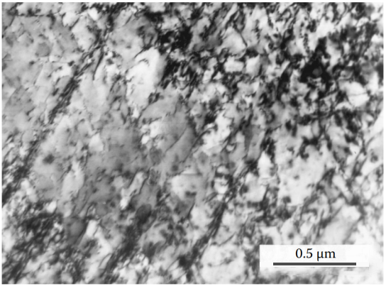
Figure 1 Dislocation distribution at 100°C is typical of low SFE metals. Some dislocations separated by SF bands slide in arrow-like shapes on the closely packed crystal planes of copper.
Stacking fault energy (SFE) is a very small-scale material property. This is expressed as γSFE and has units of energy per unit area. Stacking faults are disruptions of the normal stacking order of atomic planes in a close-packed crystal structure. These interruptions carry specific stacking fault energy. The stacking fault width is the result of the balance between the repulsive force between the two partial dislocations on the one hand and the attractive force caused by the surface tension of the stacking fault on the other hand. Therefore, the equilibrium width is determined in part by the stacking fault energy.
When SFE is high, the dissociation of a complete dislocation into two partial dislocations is energetically unfavorable, and the material may be deformed by dislocation slip or cross-slip. Materials with lower SFE show wider stacking faults, making lateral slips more difficult. SFE changes the ability of dislocations in the crystal to slide on intersecting slip planes. Low SFE reduces the mobility of dislocations in the material.

Figure 2 The planar distribution of dislocations is maintained up to 500°C. In this temperature range, thermally assisted interactions and dislocation reorganization lead to the formation of deformation bands on closely packed slip surfaces.
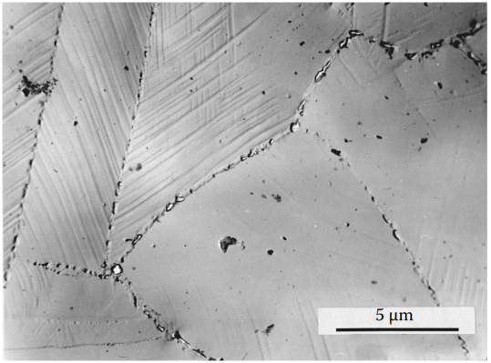
Figure 3 Plastic deformation at 500°C is accompanied by accelerated phase precipitation. A large number of tetragonal intermetallic theta phase (Mn-Ni) particles precipitate and form chains at high-angle grain boundaries and coherent and incoherent twin boundaries (shown in the replica sample). The precipitates hinder the migration of grain boundaries, thereby reducing the ductility of the alloy at this temperature.
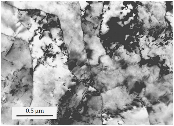
Figure 4 At temperatures from 600°C to 700°C, the SFE of the alloy increases and the dislocations move as units. Thermal activation promotes the cross-sliding and interaction of dislocations, resulting in the formation of sub-boundaries and lower dislocation density. In this temperature range, enhanced diffusion results in higher mobility of boundaries and sub-boundaries, allowing separation from precipitates. As a result, the ductility of the alloy is restored.
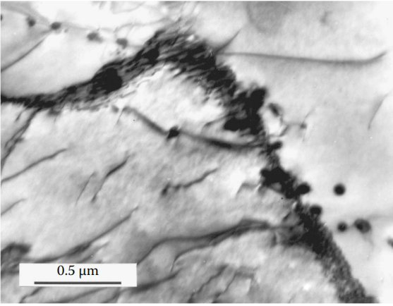
Figure 5 At 800°C, a very active diffusion process is accompanied by deformation. This structure is characteristic of dynamic recrystallization: grains with extremely low dislocation density are separated by high-angle grain boundaries. Isolated theta particles exist in some grains, but because they are not connected to the grain boundaries, they cannot hinder the migration of the grain boundaries.
Conclusion:
It turns out that the reason for the decrease in ductility and leading to edge cracking is that the temperature drops to a less ductile temperature range at the end of rolling. By combining grain refinement (modification treatment) and optimizing the hot rolling-temperature-deformation procedure, the adverse effects of grain boundary embrittlement caused by precipitation are eliminated and the hot workability of the alloy is improved.
Case 2 Distribution of strengthening phase in precipitation hardening alloy
The properties of heat-treated precipitation-hardened alloys depend largely on the distribution of strengthening phases. The reason why the industry is keen on developing aging and thermomechanical treatment technologies that can produce uniform, finely dispersed precipitates in engineering alloys is that it not only needs to improve mechanical properties but also improve corrosion resistance, toughness and fatigue resistance.
Solidification conditions are very important to the microstructure and properties of heat-treatable cast alloys. They determine the type and morphology of the main intermetallic phases and thus influence the selection of appropriate processing parameters (solution treatment and aging temperature and time), and the type, distribution and volume fraction of the aging reaction and strengthening phase depend on these parameters.
The optimal heat treatment protocol should be combined with appropriate deformation conditions to provide the best microstructure and properties of the forged product for the specific application. For example, a structure containing a high density of uniformly distributed coherent or semi-coherent fine precipitates provides high strength to an aged alloy, while the absence of large precipitates at grain boundaries ensures good resistance to intergranular corrosion, high ductility and fracture toughness.
Selecting an appropriate thermomechanical treatment for a specific alloy is another effective way to obtain finer and uniformly distributed intermediate precipitates since an increase in dislocation density provides more sites for the heterogeneous nucleation of these particles.
TEM studies on the structure of precipitation-hardened alloys can help develop and introduce into practice new optimal aging and thermomechanical treatment mechanisms, as these studies allow the evaluation of the effect of different processing parameters on the microstructure.
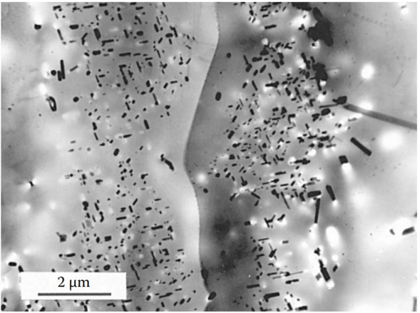
Figure 6 Aging treatment often fails to produce the ideal uniform strengthening phase distribution. For example, aluminum alloys can develop precipitation-free zones (PFZ)—areas near grain boundaries where precipitation has not occurred.
Alloy Al-6%Cu-0.2%Ti-0.2%Zr, air-cooling casting, then solid solution treatment at 540°C for 5 hours, and aging treatment at 160°C for 12 hours.
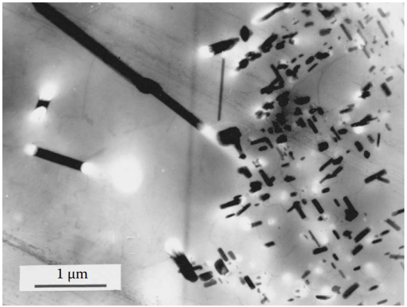
Figure 7 Air cooling of cast aluminum alloys will cause coarse intermetallic phases to precipitate at the grain boundaries, and coarse iron-containing needle-like compounds to solidify inside the grains. Coarse needle-like phases are particularly detrimental to the mechanical properties of all cast aluminum alloys because they are stress concentrators and can lead to uneven distribution of secondary strengthening precipitates. The uneven distribution of the strengthening phase after aging is usually due to uneven saturation caused by an inappropriate quenching regime.
Alloy Al-6%Cu-0.2%Ti-0.2%Zr, air-cool the mold, then solid solution treatment at 540°C for 5 hours, and aging treatment at 160°C for 12 hours.
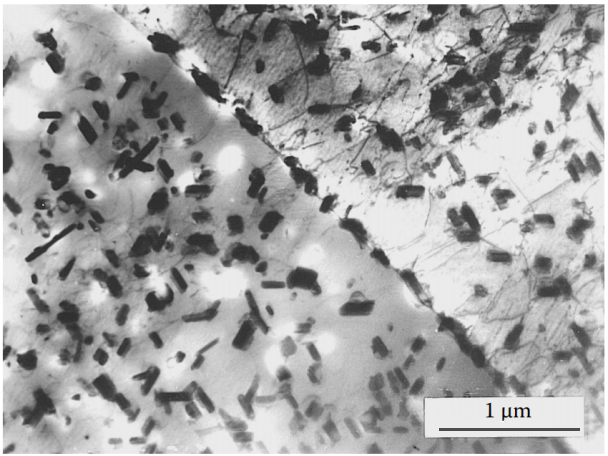
Figure 8 The quantity and distribution of primary intermetallic phases can be controlled by controlling the cooling rate of the casting method. Rapid cooling starting at a temperature slightly below the solidification temperature results in finer, more saturated primary precipitates and a more uniform distribution of the alloying elements retained in the solid solution. Alloy Al-6%Cu-0,2%Ti-0,2%Zr is die cast from 540°C and rapidly cooled, then solution treated at 540°C for 5 hours and aged at 160°C for 12 hours deal with. The uniform distribution and similar size of secondary precipitates at grain boundaries and within grains ensure better mechanical properties compared to air-cooled casting of the same alloy (Fig. 2).
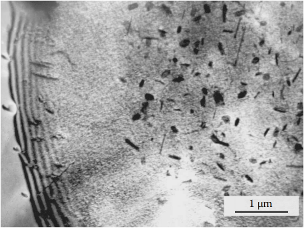
Figure 9 The high mechanical strength of this typical wrought aluminum alloy is provided by the dispersed precipitation of rod-like β′ phase (Mg2Si) and the band-like precipitation within the grains. The size of the primary intergranular Mg2Si precipitates is relatively small, but a PFZ about 2µm wide can be seen around the grain boundaries. The precipitation zone is spread throughout the grain, including the depleted PFZ region, which indicates that the precipitation zone is mainly composed of copper and chromium atoms. Alloy 6061 (Al-1%Mg-0.6%Si-0.2%Cr-0.27%Cu), after die casting, undergoes solution treatment at 510°C for 2 hours and then undergo aging treatment at 160°C for 12 hours.
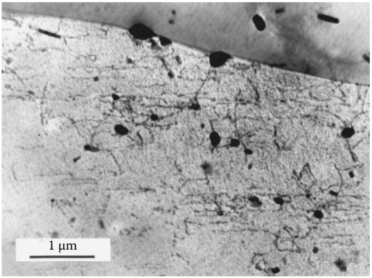
Figure 10 Cold working of the quenched alloy provides a large number of sites for the subsequent uniform nucleation of the mesophase. This effect can be used in thermomechanical treatment, which imposes a certain degree of controlled deformation before aging to improve the properties of the alloy, accelerate the aging process, and minimize the possible damaging effects of PFZ in the alloy.
Alloy 6061 (Al-1%Mg-0.6%Si-0.2%Cr-0.27%Cu) is cold forged and aged at 160°C for 12 hours. The heterogeneous precipitation of Mg2Si in the deformed structure is more uniform and there is no PFZ. The reduction in the size of the deformation zone, the transformation of the rod-like Mg2Si particle shape to a round shape, and the presence of some dislocations in the aging structure all contribute to improving the properties of thermomechanically treated alloys.
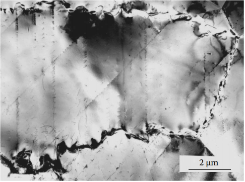
Figure 11 Phases that preferentially precipitate at grain boundaries will greatly reduce the mechanical properties of the alloy and promote intergranular corrosion. In the “sensitizing” temperature range of 500 to 900°C, high-chromium austenitic stainless steels will precipitate chromium-rich phases (carbides, nitrides, intermetallic compounds) at the grain boundaries, which is a serious problem. Austenitic nitrogen steel Fe-18Cr-14Mn-0,6N quenched from 1150°C and then tempered at 700°C for 30 minutes. The most dangerous temperature range for high-nitrogen austenitic steel is 550°C to 850°C. At this time, under the condition of nitrogen supersaturation, austenite decomposes in a discontinuous mechanism. This process begins with the precipitation of Cr2N particles on the grain boundaries.
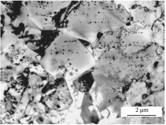
Figure 12 A large number of crystal structure defects introduced by plastic deformation before aging are the center of the nucleation of the second phase, which can change the precipitation mechanism from local grain boundary precipitation to uniform and continuous precipitation. In non-ferrous metal alloys (such as copper-beryllium alloys), it can also be observed that severe cold plastic deformation before aging inhibits honeycomb precipitation. Austenitic nitrogen steel Fe-18Cr-14Mn-0,6N quenched from 1150°C, cold worked to 75% thinner, then tempered at 700°C for 10 minutes. Severe cold working promotes the precipitation of uniformly distributed spherical nitrides inside the grains. The large number of particles provides a large number of recrystallization centers, thereby preventing grain growth. The final structure of ultra-fine grains and uniformly distributed nitrides provides the material with excellent mechanical properties and good corrosion resistance.