Optical microscope is the general term for microscopes that use visible light and glass lenses to magnify and observe objects.
Historically, optical microscopes have been used to observe organisms such as microorganisms and cells of animals and plants, so they are also called biological microscopes.
Optical microscopy uses a lens or series of lenses to magnify images of small samples in visible light. A lens is placed between the sample and the observer’s eyes to magnify the image so it can be examined in greater detail.
● Basic structure of optical microscope
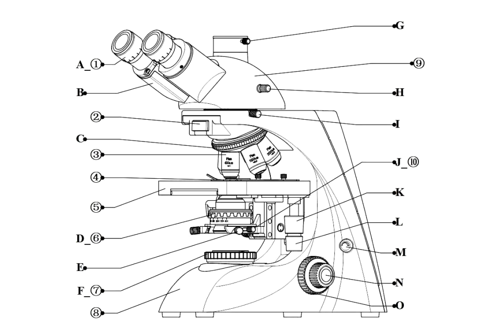
☆The numbers refer to the components of the microscope, and the letters refer to the operable and adjustable parts of the microscope.
Microscope component names:
- ① Eyepiece
- ② Accessory module box
- ③ Objective lens
- ④ Sectioning clip
- ⑤ Do not take off the stage
- ⑥ Swing-out condenser
- ⑦ Field diaphragm
- ⑧ Host
- ⑨ Trinular eyepiece observation tube
- ⑩ Condenser holder
Names of operating parts involved in the front and right-hand areas:
- A. Diopter adjustment ring
- B. Left and right eyepiece tubes
- C. Nosepiece
- D. Aperture diaphragm adjustment dial
- E. Field diaphragm centering handle
- F. Field diaphragm adjustment dial
- G. Camera eyepiece locking screw handle
- H. Camera observation conversion lever
- I. Observation tube installation locking screw
- J. Condenser mounting locking screw handle
- K. Move the handwheel longitudinally without taking off the stage
- L. Do not take off the stage lateral movement hand wheel
- M. Brightness adjustment knob
- N. Right micro focus hand wheel
- O. Right coarse focusing handwheel
1. Optical part
Including eyepieces, objectives, condensers and light sources.
(1) Eyepiece
It usually consists of two sets of lenses, the upper one is also called the “eyepiece” and the lower one is called the “field lens”. There is a field diaphragm (metal ring-shaped device) between the two or below the field lens. The intermediate image magnified by the objective lens falls on the field diaphragm plane, so an eyepiece micrometer can be added to it. The magnification factor is engraved above the eyepiece, such as 10×, 20×, etc. According to the size of the field of view, eyepieces can be divided into ordinary eyepieces and wide-angle eyepieces. The eyepieces of some microscopes are also equipped with a diopter adjustment mechanism, and the operator can adjust the diopter of the left and right eyes respectively. There are also photographic eyepieces (NFK) available for shooting.
(2) Objective lens
It consists of an array lens and is installed on the converter, also called the objective lens. Usually each microscope is equipped with a set of objective lenses with different magnifications, including:
- ① Low magnification objective lens: refers to 1×~6×;
- ② Medium magnification objective lens: refers to 6×~25×;
- ③ High magnification objective lens: refers to 25×~63×;
- ④ Oil immersion objective lens: refers to 90×~100×.
When using an oil immersion objective, a liquid with a refractive index of about 1.5 (such as cedar oil, etc.) needs to be filled between the lower surface of the objective lens and the upper surface of the cover glass. It can significantly improve the resolution of microscopic observation. Other objectives are used directly. During the observation process, the selection of objective lenses generally follows the order from low to high, because the low-power lens has a large field of view and is easy to find the specific part to be inspected. The magnification of a microscope can be roughly regarded as the product of the magnification of the eyepiece and the magnification of the objective lens.
(3) Concentrator
It consists of a condenser lens and an iridescent aperture, located under the stage. The function of the condenser lens is to focus light within the field of view; the iridescent aperture below the lens group can be opened or reduced to control the light transmission range of the condenser, adjust the intensity of light, and affect the resolution and contrast of imaging. When used, it should be adjusted according to the purpose of observation and the intensity of the light source to obtain the best imaging effect.
(4) Light source
Earlier ordinary optical microscopes relied on the reflector on the mirror base to reflect natural light or light to the center of the condenser lens as the light source for microscopic examination. A reflector consists of a flat surface and a concave surface. When a condenser is not used or the light is strong, a concave mirror is used. Concave mirrors can condense the light. When a condenser is used or the light is weak, a plane mirror is generally used. Newly produced microscopes generally have a light source installed directly on the mirror base and a current adjustment screw to adjust the light intensity. Light source types include halogen lamps, tungsten lamps, mercury lamps, fluorescent lamps, metal halide lamps, etc.
There are two types of light source illumination methods for microscopes: transmission type and reflection (epi-reflection) type. The former refers to the light source passing through a transparent microscope object from bottom to top; the reflection microscope uses the top of the objective lens to illuminate (epi-illumination) an opaque object.
2. Mechanical part
Including mirror base, mirror column, mirror wall, lens barrel, objective converter, stage and quasi-focus spiral, etc.
(1) Mirror holder
The base part is used to support the stability of the entire microscope.
(2) Mirror column
The upright short column between the mirror base and the mirror arm serves as a connection and support.
(3) Mirror arm
The arcuate part at the back of the microscope is where you hold it when moving the microscope. Some microscopes have a movable tilt joint between the mirror arm and the mirror column, which can adjust the backward tilt angle of the mirror barrel to facilitate observation.
(4) Lens tube
A cylindrical structure is installed at the tip of the mirror arm, connected to the eyepiece on the upper side and the objective lens converter on the lower side. The international standard tube length of a microscope is 160 mm, and this number is marked on the housing of the objective lens.
(5) Objective converter
The freely rotating disc at the lower end of the lens barrel is used to install the objective lens. During observation, the objective lenses of different magnifications can be exchanged by rotating the converter.
(6) Stage
The platform under the lens barrel has a circular light hole in the center. For placing slides. The stage is equipped with spring clips that fix the specimen, and a pusher on one side to move the specimen’s position. Some pushers are also equipped with scales, which can directly calculate the distance moved by the specimen and determine the position of the specimen.
(7) Quasi-focus spiral
There are two large and small spirals mounted on the mirror arm or mirror column. When rotated, the lens barrel or stage can be moved up and down to adjust the focal length of the imaging system. The large one is called the coarse focus screw, and each rotation makes the lens barrel rise and fall by 10mm; the small one is called the fine focus screw, and one turn can make the lens barrel only rise and fall by 0.1mm. Generally, when observing an object under a low-magnification lens, use the coarse focus screw to quickly adjust the object image so that it is within the field of view. On this basis, or when using a high-magnification lens, use the fine focus screw to fine-tune. It must be noted that general microscopes are equipped with two sets of quasi-focus screws on the left and right, which have the same function. However, do not turn the screws on both sides with both hands at the same time to prevent the uneven strength of the hands from causing torque and causing the screw to slip.
● Imaging principle of optical microscope
An optical microscope is essentially composed of two convex lenses, so let’s quickly review the imaging rules of convex lenses:
Imaging rules and application examples of special points and intervals of objects located in front of convex lenses
| Object distance u | Properties of image | Application examples | ||||
| Inverted, upright | Zoom in, zoom out | virtual, real | On which side of the object | image distance v | ||
| u>2f | inverted | reduce | real | different side | f<v<2f | camera |
| u=2f | inverted | same size | real | different side | v=2f | |
| f<u<2f | inverted | magnify | real | different side | v>2f | projector |
| u=f | No imaging, the light passes through the convex lens and becomes a light ray parallel to the main axis | obtain a parallel light source | ||||
| u<f | upright | magnify | virtual | same side | 0~∞ | magnifying glass |
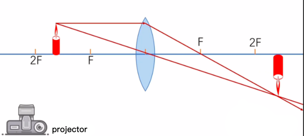
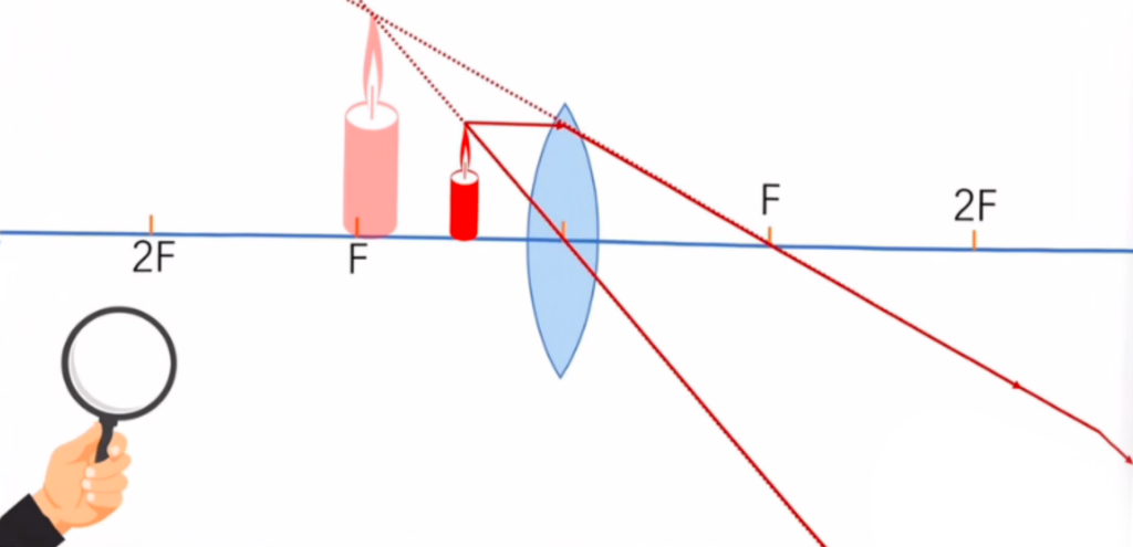
Combined with the above figure, we can see that when the objective lens of an optical microscope observes an object, the object distance is between one and two times the focal length. The image is outside the first convex lens, which is one time the focal length of the objective lens, and within two times the focal length, forming an inverted magnified real image. (i.e. projector principle); the real image falls within one focal length of the eyepiece, forming an upright magnified virtual image (magnifying glass principle). The two are combined to form a magnified and inverted virtual image.
Do you understand the imaging principle now? If you still have any questions, please send a private message to discuss!
By the way, let’s talk about the difference between high-power objective lenses and low-power objective lenses:
Compared with low-magnification objective lenses, high-magnification objective lenses are thicker, have greater curvature, smaller focal lengths, and better magnification effects.

● Types of optical microscopes
There are many types of light microscopes. They can range from very basic designs to highly complex designs that provide higher resolution and contrast. Light microscopes are classified in many ways:
- According to the number of eyepieces used, it can be divided into trinocular, binocular and monocular microscopes
- According to whether the image has a three-dimensional sense, it can be divided into stereoscopic vision and non-stereoscopic vision microscopes.
- According to the observation object, it can be divided into biological and metallographic microscopes, etc.
- According to optical principles, it can be divided into polarization, phase contrast, and differential interference contrast microscopes, etc.
- According to the type of light source, it can be divided into ordinary light, fluorescence, infrared light laser microscope, etc.
- According to receiver type, it can be divided into visual, photographic, and television microscopes, etc.
Commonly used microscopes include binocular continuous zoom stereo microscopes, metallographic microscopes, polarizing microscopes