Ⅰ Application of polarizing microscope in glass production
As one of the oldest materials known to humans, glass is used in a wide range of applications and must meet the most stringent quality standards without exception. Take optical microscopes, for example, which cannot be used without a special type of optical glass. Polarizing microscopes can quickly and cost-effectively inspect the glass to ensure the production quality of flat glass, insulating glass, and laminated glass.
1. Crystal defects
Although silicate glasses can vary widely in composition and properties, the types of potential defects and causes are similar. In addition to gaseous inclusions (bubbles), crystallized glass defects are also common in daily production. It is critical to detect defects quickly to ensure appropriate action is taken.
- Refractory contaminants in raw materials and old recycled glass
- Unmelted raw material components
- Corrosion residues of fireproof mineral materials in smelters
- Denitrification products

2. Fast and reliable fault diagnosis
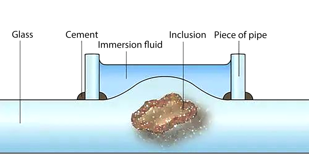
Distinguishing crystal inclusions from air bubbles or processing defects requires the use of automated inspection and sorting systems or manual sorting after visual inspection. Sections cut with a glass cutter or diamond saw can usually be examined under a microscope without further processing. For large, opaque “stones,” the defective material is ground up and then diagnosed under incident light. Smaller inclusions in glass knots are often not clearly visible due to the lensing effect of the glass beads. Therefore, the glass junction is usually covered in an immersion fluid with the refractive index of the glass (Figure 1). Additionally, the microscope configuration presented here also allows quantitative polarized light measurements; however, this requires planar polished sections of specific thickness.
We recommend using an L-shaped objective lens with a large working distance to achieve high magnification non-destructive diagnosis of defects located several millimeters below the glass surface. Using the 40x polarized objective with coverslip correction in conjunction with the 10x polarized objective allows measurements and colonoscopic observations of thin-section samples.
In a transmitted light field view, the shape, color, and relative refractive index of the surrounding glass can be determined by the relief of the inclusion. Oblique illumination can be achieved by lowering the center position of the condenser or using a variable-opening shutter to enhance contrast. Oblique lighting produces strong relief fringes that are barely visible under Kohler lighting at optimal settings.
In transmitted light polarization contrast, isotropic and anisotropic materials can be distinguished. For isotropic crystals, the extinction position can be determined, and using a lambda plate, the order of birefringence can be estimated. Incident brightfield and incident light polarization contrast are only applicable to defects on the glass surface or ground specimens. Oblique incident illumination combined with transmitted light allows the identification of surface details and the color of inclusions.
3. Examples of crystalline inclusions
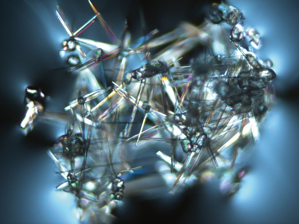
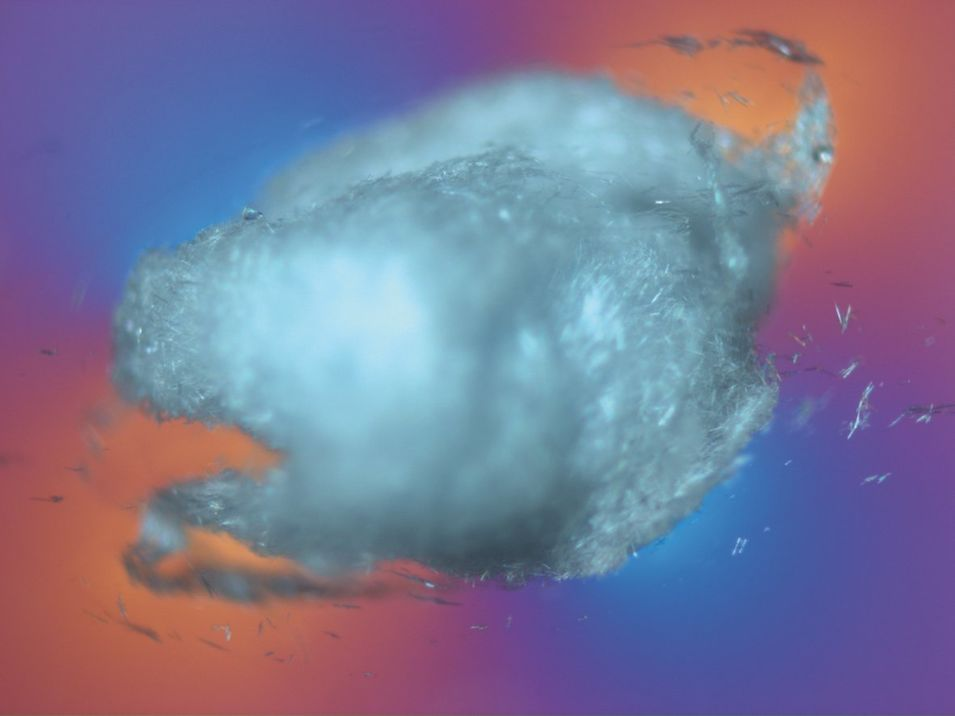
(1) Tin oxide (SnO2)
The heating electrodes in some smelters consist of refractory tin oxide. In the event of overload, the electrode material will peel off, forming a typical agglomeration of blue irregular grains (native tin oxide). At high temperatures, these substances dissolve after a short time, forming so-called knots. At lower temperatures, long prismatic tin oxide crystals (secondary tin oxide) can grow into fine needles (Figure 2) or felt-like aggregates (Figure 3).
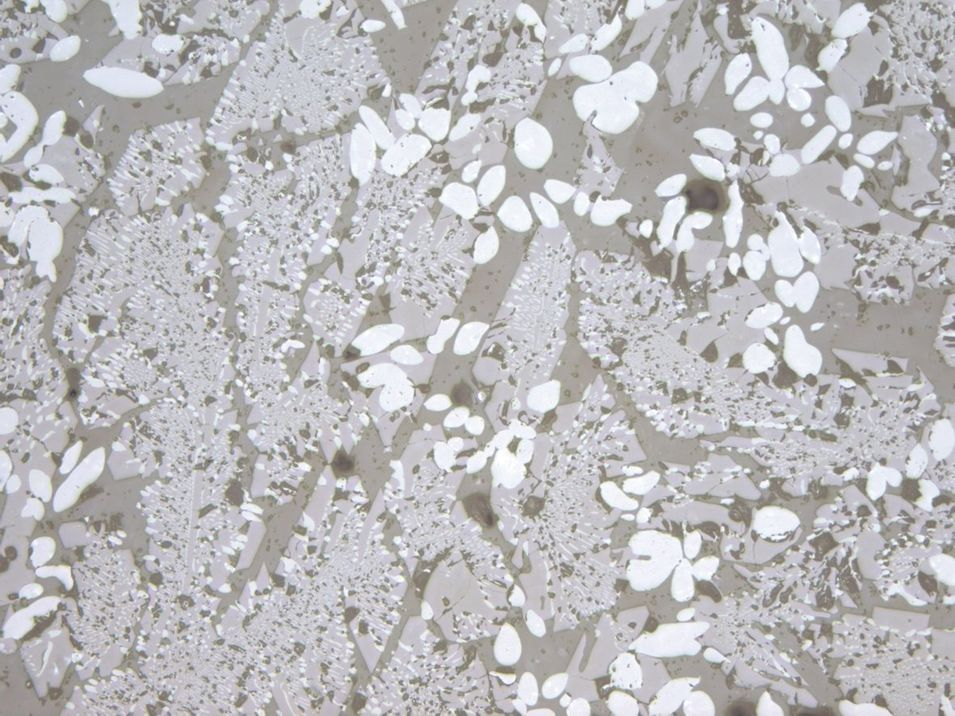
(2) Zirconium dioxide (ZrO2) and corundum (Al2O3)
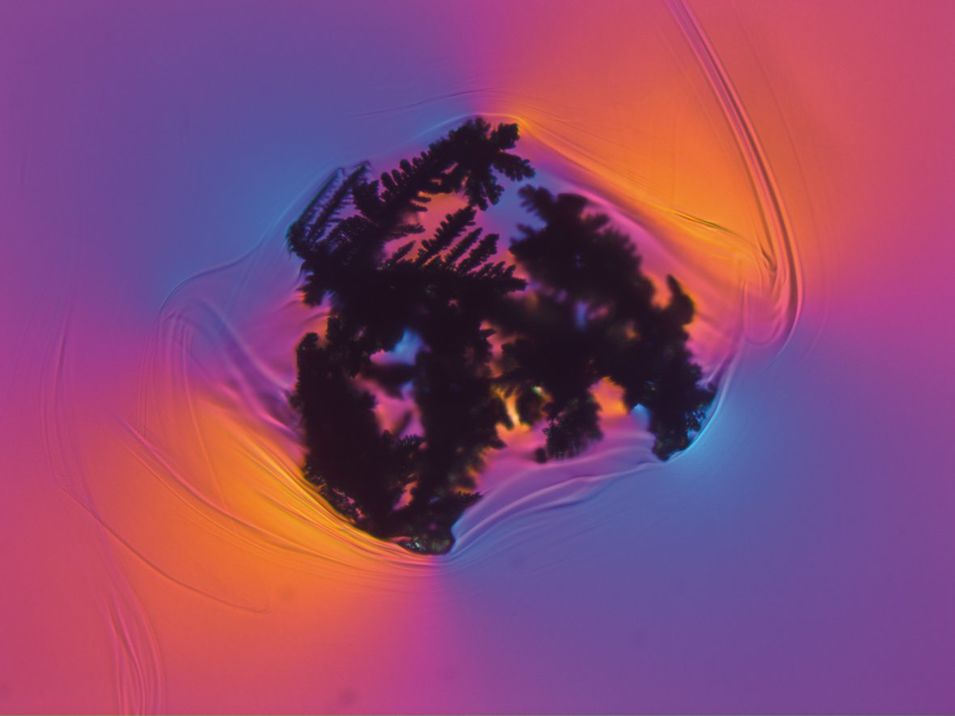
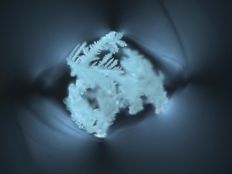
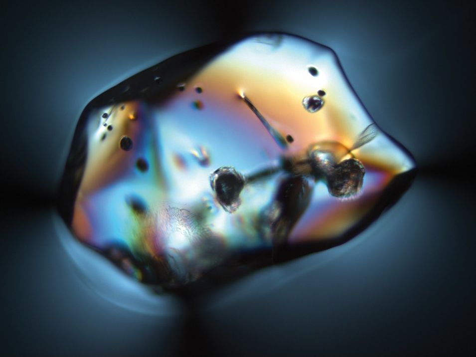
Zirconium dioxide and corundum are components of fire-resistant minerals in smelters (Figure 4). Under normal loading, the highly resistant zirconium dioxide dissolves in a slow, well-tempered manner. A large number of zirconium dioxide glass defects indicate strong localized corrosion, for example, due to thermal overload or excessive flow. Zirconium dioxide appears as small white inclusions in its original compound, or forms typical dendrites (Fig. 5 ). Corundum dissolves more easily in the glass furnace, often forming knots and streaks in the glass. However, corundum can also take the form of rounded particles with typical inclusions (Figure 6).
(3) Tridymite/cristobalite
Tridymite, and less commonly columnar spar, forms as denitration products on silica-rich glasses, for example, when volatile components such as alkalis or boron oxides evaporate. Tridymite forms crystal aggregates with typical 60° angles (Fig. 7).

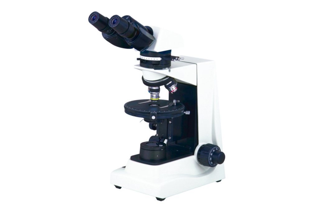
Ⅱ NP-400 polarizing microscope
The NP-400 polarizing microscope can observe the crystal shape, color, interference color, etc., of minerals under single polarization, orthogonal polarization, and convergent light, and accurately identify the optical properties of various minerals or other thin samples.
The product is easy to use, fully functional, and widely used in the inspection of geology, petroleum, coal, chemical fibers, medicine, pharmaceuticals, and other fields, as well as in teaching and scientific research in related disciplines of higher education institutions.
Ⅲ Performance of NP-400 polarizing microscope
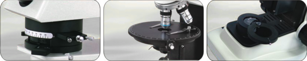
- 0°-90° swing-type polarizer, which can swing out the light path for single polarization observation, and is equipped with an inlet test plate, a 1/4λ test plate, and a quartz wedge test plate.
- Circular rotating stage, diameter Φ145mm, 360° equal division scale, vernier grid value 6′
- The polarizer can be arranged to adjust the light path; 6V/20W halogen lamp illumination can adjust the brightness and observe specimens under different polarized lights.
Ⅳ Technical parameters of NP-400 polarizing microscope
| Viewing Head | Monocular head inclined at 30° |
| Hinged-type binocular head inclined at 30° | |
| Hinged-type trinocular head inclined at 30° | |
| Eyepiece | Eyepiece WF10X/18 with scale of crosshair |
| WF10X/18 | |
| Objective | Strain free achromatic objective 4X, 10X, 40X, 60X |
| Nosepiece | Backward quadruple nosepiece |
| Analyzer | Rotatable analyzer with gradation 0°-90° |
| Bertrand Lens | Bertrand lens, sliding in/out of optical path |
| Optical Compensator | λ Slip (first class red), 1/4λ Slip quartz wedge |
| Revolving Round Stage | Diameter Φ 145mm, 360° rotatable and graduated in 1° increments, minimum resolution 6′ when using vernier scale, center adjustable |
| Condenser | Abbe condenser NA 1.25 with iris diaphragm & fiter |
| Focusing | Coaxial coarse & fine adjustment, range 28mm, fine division 0.002 |
| Polarizer | Abbe condenser NA 1.25 with iris diaphragm & filter |
| Illumination | 6V/ 20W Halogen lamp, brightness adjustable |