§1 Propagation of light
1. Reflection
When light propagates to different materials, it changes the direction of propagation at the interface and returns to the original material. This phenomenon is called the reflection of light. The reflected ray is on the same plane as the incident ray and the normal; the reflected ray and the incident ray are separated on both sides of the normal; the reflection angle is equal to the incident angle. Light is reversible. In the phenomenon of light reflection, the optical path is reversible.
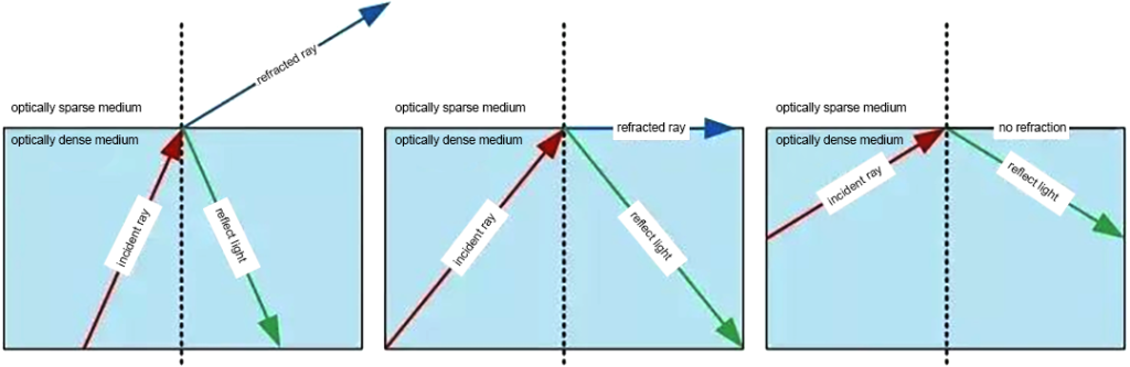
2. Refraction
When light is incident obliquely from one transparent medium into another transparent medium, the direction of propagation generally changes. This phenomenon is called refraction of light. The speed of reflected light is the same as that of incident light, while the speed of refracted light is different from that of incident light.
3. Interference
Interference is a phenomenon in which two or more waves overlap in space and form a new waveform.
When two columns of light waves with the same frequency meet in the air, they are superimposed. They are always strengthened in some areas and weakened in other areas. The phenomenon of light and dark stripes or colorful stripes is called light interference. Only coherent light sources with the same frequency, constant phase difference, and consistent vibration direction of the two columns of light waves can produce light interference.
4. Diffraction
When light encounters an obstacle or a small hole during propagation, the light will deviate from the straight path and propagate behind the obstacle. Only when the size of the small hole or obstacle is similar to or smaller than the wavelength of the light wave can significant diffraction occur.
§2 Modern microscopy imaging technology
Microscopes can be divided into optical wide-field microscopes, confocal microscopes, and stereo microscopes based on imaging methods [1]. Optical wide-field microscopes and confocal microscopes are more used in life science research and have higher requirements for imaging, while stereo microscopes are more used in industrial fields and have higher requirements for digitalization and humanization.
1 Optical wide-field microscope
Among the various imaging techniques in optical wide-field microscopy, brightfield, darkfield, polarization, and fluorescence imaging are used to make the specimen structure that needs to be observed visible, while phase contrast, differential interference, and modulation contrast imaging are used to make the structure of the specimen visible. Phase changes show up. In many cases, several imaging techniques are used simultaneously.
1.1 Brightfield imaging and darkfield imaging
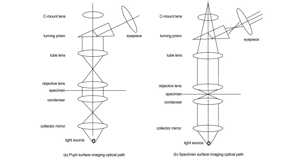
Brightfield imaging is the most basic microscopic imaging technology, and all other imaging technologies are based on brightfield imaging. The light path of bright field imaging is shown in Figure 1. The light source is focused on the specimen through the condenser and condenser. If it is critical illumination, the image of the filament will be directly focused on the specimen; if it is Kohler illumination, the image of the filament will be focused on the front focal surface of the condenser. The condenser then illuminates the specimen. The light transmitted through the specimen is collected by the objective lens and forms an image of the pupil on the back focal plane of the objective lens. The image of the pupil is the distribution of the imaging light angle relative to the space. This position is often used in modern microscopes to change various contrast methods. After passing through the back focal plane, the light enters the barrel lens, and the barrel lens transforms the angular distribution relative to space into the position distribution relative to space, that is, an intermediate image plane is formed on the back focal plane of the barrel lens. In modern microscopes, before the tube lens forms an intermediate image plane, a C-mount lens is used to transfer the intermediate image plane to the camera, thereby realizing digital imaging and facilitating modern teaching and research. Finally, the intermediate image plane is imaged by the eyepiece onto the retina of the eye, thereby seeing a magnified image.
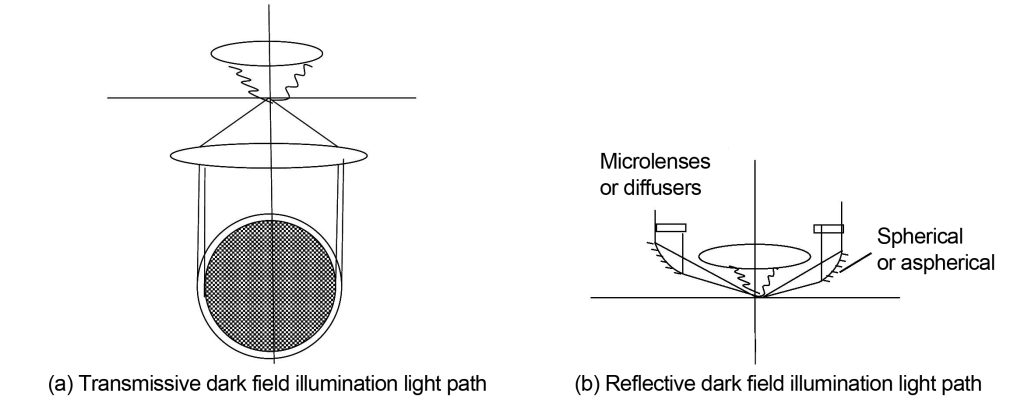
Only the lighting path differs between darkfield imaging and brightfield imaging. Darkfield imaging is illuminated at an angle beyond the numerical aperture of the objective lens. The specimen produces diffracted light or scattered light due to large-angle illumination. The diffracted light or scattered light contained within the numerical aperture of the objective lens is collected by the objective lens and projected to the eye or camera according to the brightfield light path. . Darkfield illumination is shown in Figure 2. There are two methods: one is transmissive darkfield illumination, which directly intercepts light at the front focal surface of the condenser with an opaque ring in the middle; the other is reflective darkfield illumination, The dark field reflecting mirror is installed on the objective lens housing close to the specimen. The light passes through the dark field reflecting mirror and is incident on the specimen at an angle exceeding the numerical aperture of the objective lens. The diffracted or stray light emitted by the specimen is collected by the objective lens and then imaged. Some reflective dark field illumination mirrors are spherical, some are aspherical, and some add microlenses or diffusers to the illumination light path, all in order to achieve uniform illumination of a large area.
1.2 Phase contrast imaging
The phase contrast imaging optical path is shown in Figure 3. Phase contrast imaging is at the back focal plane or the conjugate position of the back focal plane of the objective lens, that is, the position of the light angle relative to the spatial distribution (pupil position). Select the light from a certain annulus to pass through this annulus at level 0 The light intensity is reduced to the same as the first-order diffracted light, and then the phase of the 0-order light is changed by 180°, which is opposite to the phase of the first-order diffracted light. In this way, when the light undergoes phase and intensity transformation on the pupil plane, the tube lens synthesizes it according to its spatial position, and the structural characteristics represented by the first-order diffracted light will be highlighted in the intermediate image plane. At the same time, because the 0-order light becomes weaker , the background will be darker.
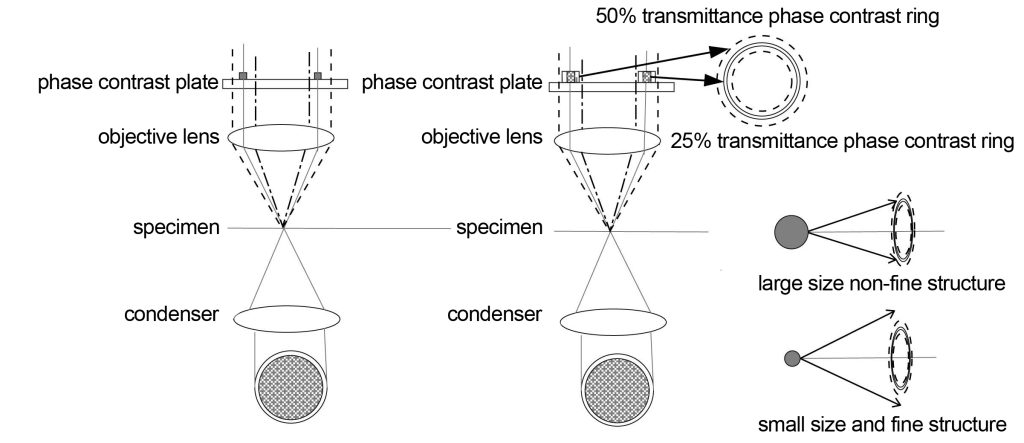
Different orders of diffracted light are separated after passing through the specimen (similar to the function of a grating). The intensity and phase of the 0-order diffracted light change after passing through the phase contrast ring in the objective lens. The width of the objective lens phase contrast ring is smaller than that produced by a certain characteristic structure. The width corresponds to the diffraction angle, so that the first-order diffracted light corresponding to the 0-order light can maintain the same intensity and phase. For the characteristic structure between these angles, the first-order diffracted light will partially produce changes in intensity and phase. When combined with the 0-order diffracted light, a halo will be produced, and the smaller the angle, the greater the impact of the halo. This is a drawback of phase contrast imaging. Generally, a suitable phase contrast ring width will be found based on experience, and the halo and imaging details will be better balanced.
It is precisely because of this characteristic of phase contrast imaging that only the phase changes of certain structures can be reflected by phase contrast imaging. Generally, it is easier to reflect the internal structure of cells through phase contrast imaging, but it is not easy to reflect the boundaries of cells. Other structures, especially the small-angle structures mentioned above, have more or less halos.
Nikon has adopted an apodized phase contrast imaging method to further reduce the transmittance of light at small angles. Light at small angles corresponds to large-sized structures, that is, the intensity of non-fine structures is reduced. At the same time, light at large angles corresponds to Small size i.e. fine structures are more easily visible.
1.3 Polarized imaging
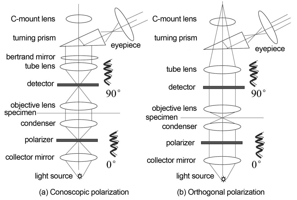
Polarized imaging, as the name suggests, uses polarized light for imaging. Polarized imaging is divided into two types: orthogonal polarization and conoscopic polarization. The optical path is shown in Figure 4. Cross-polarization means that after the linearly polarized light passing through the polarizer passes through the condenser, specimen, and objective lens, the polarization characteristics of the specimen will change the vibration direction of the original linearly polarized light, and only the polarized light perpendicular to the vibration direction of the original linearly polarized light will It can pass through the polarizer at the back and be received by the eyepiece. Cross-polarization is a polarization imaging method that is observed directly through the eyepiece. Another type of conoscopic polarization refers to using a Bertrand mirror and an eyepiece to directly observe the polarized light imaging on the back focal plane of the objective lens. The rest is the same as the orthogonal polarization. Since what is being observed is the imaging situation on the back focal plane of the objective lens, it is equivalent to observing how the angle of light on the specimen surface changes with space, so it is called conoscopic polarization. Conoscopic polarization is generally used with large numerical aperture objectives.
Polarized imaging has few applications in the field of life sciences and is mainly used in geological materials research.
1.4 Differential interference imaging
Differential interference also converts the phase difference of the specimen into amplitude changes for imaging, which is the same as phase contrast imaging. However, differential interference only modulates 0-order light, while phase contrast imaging modulates 0-order light and 1-order light.
Figure 5 shows the optical path diagram of differential interference imaging. On the basis of bright field imaging, a polarizer and a Wollaston prism are placed on the front focal surface of the condenser. Linearly polarized light is divided into ordinary light o light and extraordinary light e light, and their vibration directions are 90°. The o-light and the e-light converge on the specimen through the condenser. The birefringence or phase deviation of the specimen will affect the relative vibration directions of the o-light and the e-light. That is, the o-light and e-light are no longer oscillating at 90° to each other. , or the o-light or e-light has a slight phase difference. The phase information of the specimen is brought into the optical path, and then passes through the second Wollaston prism, so that the o-light and e-light have the same vibration direction, so that the o-light or e-light with phase difference will interfere, and the phase Changes are converted into changes in amplitude. However, due to the change in vibration direction, some light does not interfere after passing through the second Wollaston prism and becomes stray light. Therefore, a polarizer is required to select for interference, and the light perpendicular to the polarization direction of the incident light enters the lens tube. Lenses and eyepieces. In practical applications, Wollaston prisms are replaced by Nomarski prisms, which can ensure a suitable working distance.
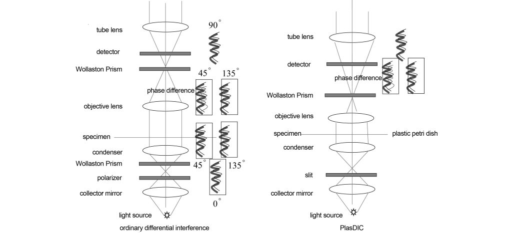
Since o-light and e-light are two beams of light at different positions separated by the Wollaston prism, that is to say, o-light and e-light will be imaged separately. When they are synthesized by the second Wollaston prism, due to the Due to the displacement effect, the image formed will be displaced in the X and Y directions, producing a relief effect. Therefore, if the relative position of the Wollaston prism is adjusted, the relief effect can be adjusted.
Differential interference first differentiates and then interferes. It first changes the phase into a change in phase (i.e., phase difference), and then changes the phase difference into an amplitude change through interference. In phase contrast imaging, the phase of the reaction structure is directly converted into a change in the background light by reducing the intensity of the background light. The method appears (which is also essentially interference). Therefore, differential interference easily reveals the boundaries of cells, because the phase changes of o-light and e-light on the boundary are large, while the phase changes of the internal continuum medium on o-light and e-light are small. However, phase contrast imaging directly displays the phase, so usually, the internal fine structure has a larger phase angle and is easier to display through the phase contrast method.
Differential interference’s dependence on phase difference is both its advantage and disadvantage. Especially in the case of linearly polarized light, only the phase difference that is the same as the polarization direction can appear. After Zeiss uses circularly polarized light (C-DIC), the phase difference in all directions is revealed, which better balances differential interference and polarization.
Ordinary differential interference also requires a special objective lens, which can only achieve better differential interference effects within a small focal depth, and is only suitable for specimens with plastic petri dishes. These have restricted the application of differential interference. Zeiss provides a PlasDIC differential interference method in patent DE 10219804 and literature and has been successfully commercialized. Only a polarizer and Wollaston prism are needed to achieve the DIC effect. It only requires an ordinary objective lens and is also suitable for specimens with plastic petri dishes. However, a slit must be used in front of the condenser, and the numerical aperture of the objective lens cannot be too large, so only objectives smaller than 40X are available. The only pair of Wollaston prisms and polarizers are placed between the objective lens and the tube lens. Unpolarized light only becomes polarized light after passing through the objective lens and the Wollaston prism and is divided into o light Since the e-light is generated by slit illumination parallel to the Wollaston prism, the o-light and e-light here also have vibration directions that are 90 degrees different. At the same time, since the o-light and e-light have passed through the specimen, a phase difference has occurred. Therefore, when the polarizer makes the o-light and e-light vibrate in the same direction, interference occurs, resulting in an amplitude change relative to the phase change.
1.5 Modulation contrast imaging
The modulation contrast optical path is shown in Figure 6. The modulation contrast imaging is also on the back focal plane of the objective lens or the conjugate plane of the back focal plane. For obliquely incident slit light, the intensity of the +1 order diffracted light is greater than the background light, -1 order. The intensity of the diffracted light is less than the background light, thus creating a relief effect. Modulated contrast imaging can also be used with a polarizer and polarizer, and the relief effect can be adjusted by rotating the polarizer. Modulation contrast imaging is suitable for isotropic and isotropic specimens, while differential interference is only suitable for isotropic specimens.
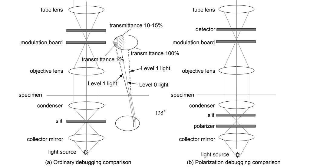
Modulation contrast and phase contrast imaging are similar to using 1-level or -1 level light for adjustment. Compared with DIC, which uses 0-level light, the energy is much lower. Therefore, the effect of modulation contrast imaging is not as good as DIC, but because of its low requirements on the objective lens , does not require complex prisms, has a wide range of applications, and is still widely welcomed.
1.6 Fluorescence imaging
Fluorescence imaging is an imaging technique under epi-light illumination. The light source is usually a mercury lamp or LED. In many cases, fluorescence imaging specimens must be stained with a variety of fluorescent dyes (there are also autofluorescent substances, but the autofluorescence energy is weak). Different fluorescent dyes will attach to different structures in cells that need to be observed. Different fluorescent dyes will produce fluorescence of different wavelengths when excited by light of different wavelengths, so that various attached cell structures can be observed. Usually, multiple wavelengths of light are used for excitation to obtain fluorescence images of multiple wavelengths, and then the images are synthesized to obtain specimen images of multiple colors. The most important components in fluorescence imaging are excitation filters and cutoff filters.
Figure 7(a) shows ordinary fluorescence imaging. The fluorescent light source mercury lamp or LED enters the objective lens through the epi-illumination light path through the dichroic prism and excites the specimen to produce fluorescence, which returns to the objective lens and is imaged through the tube lens. The light incident on the objective lens will be filtered out by the excitation filter to excite light of a certain wavelength. The fluorescent dye excited by the excitation light will produce fluorescence in different bands. The cut-off filter will cut off the light in other bands, and finally the excited Fluorescence reaches the tube lens. Due to the wavelength difference between the excitation light and the excited fluorescence, the cut-off filter can select the excited fluorescence and cut off the excitation light at the same time.
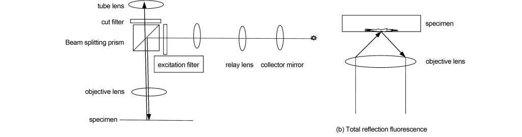
In fluorescence imaging, because the excited fluorescence comes from different focal plane positions, especially for thick specimens, the contrast of the image on the real focal plane will decrease. Total reflection fluorescence technology utilizes evanescent wave illumination with total reflection light transmitted through the medium. The evanescent wave only penetrates 100 nm into the specimen, which can effectively prevent the influence of excited fluorescence that is not in focus on the image contrast. Total reflection fluorescence is shown in Figure 7(b). Its technology requires that the numerical aperture of the objective lens be above 1.45, and it can only image adhesive specimens, otherwise, the evanescent wave cannot be illuminated.
Fluorescence imaging is also widely used in confocal microscopy and super-resolution microscopy.
2 Confocal microscopy
The purpose of confocal microscopy is to reduce the halo outside the focus and only illuminate points of diffraction-limited size for imaging. The principle of confocal microscopy was invented as early as the early 1950s. However, due to the constraints of laser technology, computer technology, and digital imaging algorithms, it was not until 1987 that the first commercial confocal microscope appeared. After the 1990s, the development of large-capacity storage technology, display enhancement technology, and computer processing technology brought broader applications to confocal microscopes.
2.1 Fluorescence confocal imaging
Confocal is mainly used in fluorescence confocal imaging. The so-called confocal means that the emission light source point, the object point on the focal plane and the detector imaging point are all focused together. The light path of the confocal microscope is shown in Figure 8. The continuous laser light source passes through the aperture aperture and is focused on the sample by the spectroscope. The spectroscope moves in the X and Y directions to scan points on the specimen. The illuminated specimen excites fluorescence and converges it on the detector. There will also be a lot of excited fluorescence produced above and below the imaging focal plane of the objective lens. These fluorescences are not confocal with the imaging point on the detector. Only a small part of this non-confocal fluorescence can pass through the small aperture diaphragm in front of the detector, so Most of the non-confocal fluorescence was not imaged. In traditional fluorescent lighting, the entire specimen is illuminated, so that fluorescence generated above and below the focal plane is detected, reducing the contrast of the focal plane image.
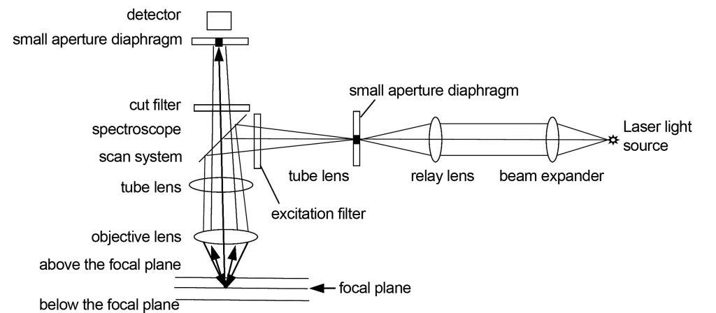
The laser light source in the confocal microscope must accurately illuminate the back focal plane of the objective lens after beam expansion. This is one of the most stringent requirements of the confocal microscope. The purpose is to ensure uniform and telecentric illumination. The small aperture diaphragm in front of the detector serves as a spatial filter, and its position must be perfectly conjugate with the position of the focal plane of the objective lens, so as to ensure that the excited fluorescence on the focal plane is accurately received by the detector. The small aperture diaphragm is available in a variety of sizes to adapt to the diffraction limit requirements of objective lenses with different numerical apertures.
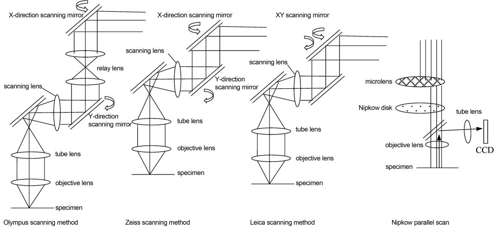
The spectroscope scanning system of a confocal microscope is one of its key and complex components. Its scanning speed and accuracy directly affect the efficiency and image quality of confocal imaging. The spectroscope scanning system not only plays the role of turning light, but also needs to scan the focus point in the X and Y directions, and the pupil of the objective lens must be accurately illuminated during the scanning process. The principle of scanning the specimen is to rotate the angle of the reflector on the back focal plane of the specimen or the conjugate plane of the back focal plane to achieve a two-dimensional translation of the imaging point on the specimen. Changes in angle on the back focal plane correspond to changes in displacement on the imaging plane. There are at least three scanning devices in commercial confocal microscopes as shown in Figure 9. Olympus uses a relay lens plus two scanning mirrors, Zeiss uses two closely spaced scanning mirrors to rotate, and Leica uses a scanning mirror to rotate two-dimensionally. The above is serial scanning, which is slow. There is a parallel scanning method that uses a Nipkow disk and a microlens. There are many small holes carved on the disk, which can scan multiple imaging points at the same time. The speed is greatly improved, but the energy loss is large. , commercial use restricted.
Confocal microscopes cannot observe specimens through the eyepieces like ordinary optical wide-field microscopes. It reconstructs the image obtained by multi-point scanning and then uses a computer to complete the image display. Therefore, it requires a large image storage space and complex computer image processing technology.
2.2 White light confocal imaging
Ordinary fluorescence confocal imaging requires the use of 3 to 5 fluorescent dyes for simultaneous detection. Different fluorescent dyes have different requirements for excitation light and emitted light, that is, they need light sources with different spectra. In ordinary microscopes, the method of changing filters is used to obtain light sources of different wavelength bands. However, the mechanical switching speed of the filters is slow and may cause image plane deviation. Moreover, the filters are exposed to moisture, high temperature, and high energy irradiation. The environment may also change the filtered wavelength. White light confocal technology is a tunable spectrum technology that uses acousto-optic devices. The wavelength and intensity are adjustable, and it can overcome almost all the shortcomings of ordinary filters.
One of the key devices in white light confocal technology is an acousto-optic device that switches different spectra. The acousto-optic device is a special birefringent crystal. By controlling the frequency of sound loaded on the crystal, the diffraction performance of the crystal can be changed. This enables rapid wavelength conversion.
The acousto-optic device used in microscopes is a piezoelectric sensor bonded to tellurium dioxide or quartz crystal. When radio frequencies are applied to a piezoelectric sensor, the piezoelectric sensor generates high-frequency sound waves that cause periodic distributions of the material’s refractive index in tellurium dioxide or quartz crystals. Changing the frequency of the piezoelectric sensor applied to the crystal can change the periodic distribution of refractive index changes. According to the phase matching conditions of the acousto-optic crystal, the wavelength of the emitted light is determined by the following formula
λ=VΔn/f (1)
In the formula: λ is the central wavelength of the emitted light; V is the propagation speed of sound waves in the crystal; f is the frequency of sound waves; Δn is the birefringence of the crystal. Therefore, when the period of change of the refractive index of the crystal changes, the wavelength of the emitted light will change.
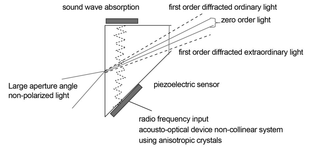
The acoustic-optical devices in modern microscopes are non-collinear systems and anisotropic crystals, as shown in Figure 10. Compared with the collinear system, the non-collinear system can separate the incident light and the outgoing first-order diffracted light at a certain angle in the case of non-polarized light, so that there is no need for a polarizer. Compared with isotropic crystals, anisotropic crystals can maintain a narrow spectral bandwidth when the incident light aperture is larger. Illumination with a certain bandwidth is one of the necessary conditions for fluorescence excitation, so collimated light is required when using isotropic crystals, but not when using anisotropic crystals.
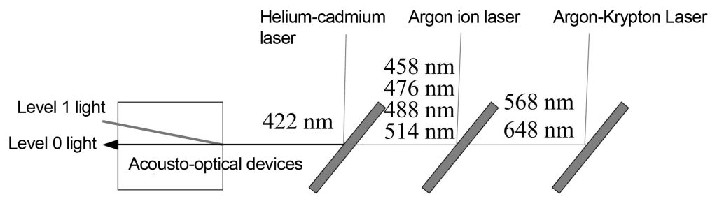
The application of acousto-optical devices in white light confocal systems is shown in Figure 11. Three laser light sources are coupled into the acousto-optic filter through the color separation plate. Helium-cadmium lasers, argon ion lasers and argon-krypton lasers co-incident 422 nm, 458 nm, 476 nm, 488 nm, 514 nm, 568 nm and 648 nm into the acousto-optical device through a color separation plate, and the acousto-optical device adjusts the radio frequency Adjust the wavelength of the output light. The 0-order light output by the acousto-optical device is absorbed by the optical trap, while the 1-order diffracted light is exported from the optical fiber to illuminate the sample.
2.3 Multiphoton confocal imaging
In ordinary confocal microscopes, since the specimen is directly irradiated by continuous laser light, the cell structure may be damaged, especially in many fluorescences that require ultraviolet light excitation, which will cause greater damage to the specimen. Multi-photon confocal technology excites the specimen with long-wavelength photons, and the energy of long-wavelength photons is lower than that of short-wavelength photons, which can reduce damage to the specimen.
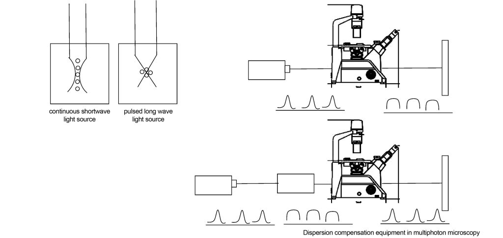
Replace the ordinary continuous laser light source in the confocal microscope with a long-wavelength pulsed light source, such as replacing the 350nm continuous laser light source with a 700nm pulsed light source. In this way, the specimen needs to absorb two photons to achieve the same energy generated by the 350nm light source, that is, The energy density of 700nm photons in the specimen is large. In a continuous light source system, the probability of laser excitation has a linear relationship with the photon density; in a two-photon system, the probability of fluorescence excitation has a square relationship with the photon density. That is to say, outside the focal plane of the specimen, two photons The photon density of the system decreases faster than that of the continuous light source system. In this way, the two-photon system has a better suppression effect on stray light caused by fluorescence excitation outside the focal plane, and the contrast of the image is better.
The multi-photon confocal microscope is also equipped with a dispersion compensator, as shown in Figure 12. This is because the optical elements in the optical system (such as attenuators, prisms, lenses, etc.) have a dispersive effect on light waves. After a pulsed light source of a certain frequency enters the optical system, it will be broadened, the energy will be reduced, and the fluorescence excitation effect will become worse. This dispersion compensator makes the final laser pulse incident on the specimen and the light source as consistent as possible by compensating the dispersion of the optical element.
Dispersion compensators [7] can be implemented using coated mirror kits. When laser pulses are composed of different wavelengths, the nonlinear wavelength dependence of the refractive index of these media causes pulse broadening as it passes through the glass components of the optical system. For typical optical glasses, the shorter the wavelength, the higher the refractive index. , causing short waves to propagate slower than long waves. By optimizing the coating of the mirror package, the group velocity of the long waves can be delayed more than that of the short waves, so that the long and short waves have the same speed. The group delay dispersion of light waves after reflection by the optical film system is
In the formula: φr is the reflection phase; ω is the light wave frequency. The reflection phase is related to the film thickness, refractive index and beam incident angle. Therefore, by optimizing the film system and selecting the appropriate film thickness, refractive index and beam incident angle, the required compensation dispersion can be obtained.
Of course, the dispersion compensator can also be implemented with gratings or prisms, but prism compensation for dispersion will introduce higher-order dispersion, and grating compensation for dispersion will cause greater losses, and the structure cannot be made very compact.
2.4 CARS confocal imaging
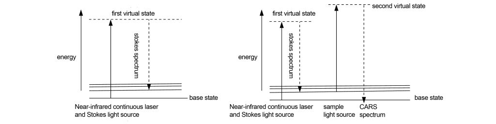
Whether it is fluorescence confocal or multi-photon confocal, the specimen needs to be fluorescently stained or labeled, which will have an impact on the specimen. Continuous Anti-Stokes Raman Scattering (CARS) confocal imaging technology, by amplifying the Raman scattering spectrum of the specimen and imaging it, does not require fluorescent staining or labeling, thus better protecting the specimen.
The main difference between CARS confocal imaging and ordinary confocal imaging is the laser light source. The principle of CARS confocal imaging is shown in Figure 13. A near-infrared continuous laser and a Stokes laser are used to illuminate the specimen simultaneously. The molecules excited by the near-infrared laser transition to the first virtual excited state, and then immediately return to the Stokes state. At the low energy vibration level represented by the X laser. By adjusting the wavelength of the near-infrared continuous laser, different low-energy vibration levels can be obtained, but they are all higher in energy than the Stokes vibration level. These low-energy vibration levels carry chemical information about the specimen. In order to image these different low-energy vibration level molecules, the specimen is illuminated with a sampling beam (the sampling beam can be the same as the near-infrared continuous laser used for excitation). Those The molecules at the low-energy vibrational level will jump to a new virtual excited state. Due to the continuous irradiation of the low-energy vibrational energy level, the newly transitioned molecules directly return to the ground state and release energy to emit photons. Due to the energy of the photon It is higher than the near-infrared continuous laser used for excitation, so the emitted spectrum will move to short wavelength, which is the anti-Stokes spectrum. Due to continuous excitation, the CARS signal is 100,000 times stronger than the traditional Raman scattering signal, which is enough for imaging.
3 Super-resolution microscopy imaging
All of the above microscopic imaging methods are limited by the diffraction limit. However, super-resolution microscopy imaging changes the imaging principle at the molecular level and breaks through the diffraction limit. Two types of super-resolution microscopy imaging are introduced below, namely stimulated emission quenching (STED) and single molecule return following ground state quenching microscopy (GSDIM).
3.1 STED
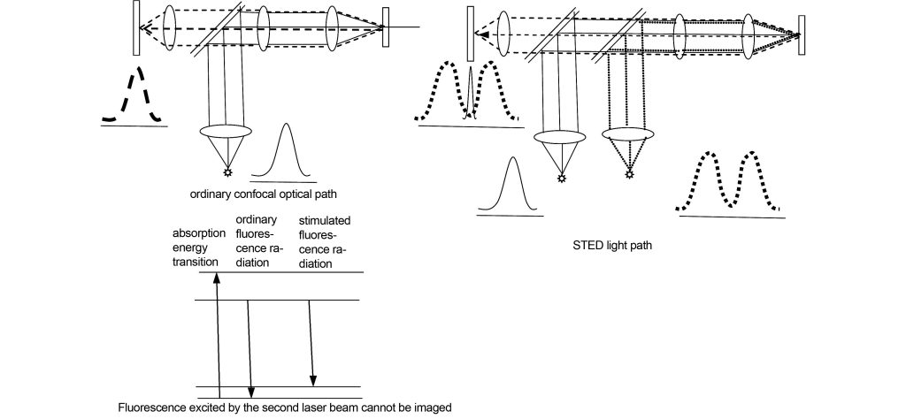
The principle of STED imaging is shown in Figure 14. The specimen is excited by the first laser beam to produce fluorescence, forming a diffraction-limited circular spot. This position is simultaneously excited by the second laser beam with a divergence angle of a circle. The second laser beam can excite the non-center of the spot formed at the same irradiation position. area, producing light waves that cannot be collected by the detector, and the diameter of the central area of the light spot can become infinitely small due to the encroachment of the non-central area, thus breaking through the Rayleigh diffraction limit.
3.2 GSDIM
The physical explanation of the Rayleigh diffraction limit is: the transition of an electron from the excited state to the ground state is approximately on the order of nanoseconds, and the response time of the detector is generally on the order of milliseconds, so all fluorescence emitted at different times will be received by the detector and Display, and the position of the fluorescence emitted at different times will be slightly different, which results in the broadening of the imaging spot, which is the origin of the diffraction limit. That is to say, if the detector can record the fluorescence emitted at a certain time, rather than all different times, then the spot will be very narrow and the diffraction limit will be exceeded.
The GSDIM imaging principle is shown in Figure 15. Normally, the greater the laser energy, the greater the emitted fluorescence. However, after reaching a certain limit, the fluorescence energy decreases. This is because when the fluorescence energy and the energy of the excitation light source change linearly, the electrons transition between the first excited state and the ground state. However, if there are enough electrons with reverse spin in the triplet state, resulting in almost no electrons in the first excited state and ground state, the fluorescence energy will decrease as the excitation energy increases. If the excitation energy is further increased, the few electrons in the ground state will jump thousands of times between the ground state and the first excited state after absorbing the excitation light, which will produce high-energy stimulated fluorescence, that is, a photon burst. A photon burst is the enhancement of the fluorescence emitted at a certain time. The fluorescence that should be emitted at other times enters the triplet state and no longer emits light. In other words, the spot formed by the enhanced fluorescence breaks through the diffraction limit.
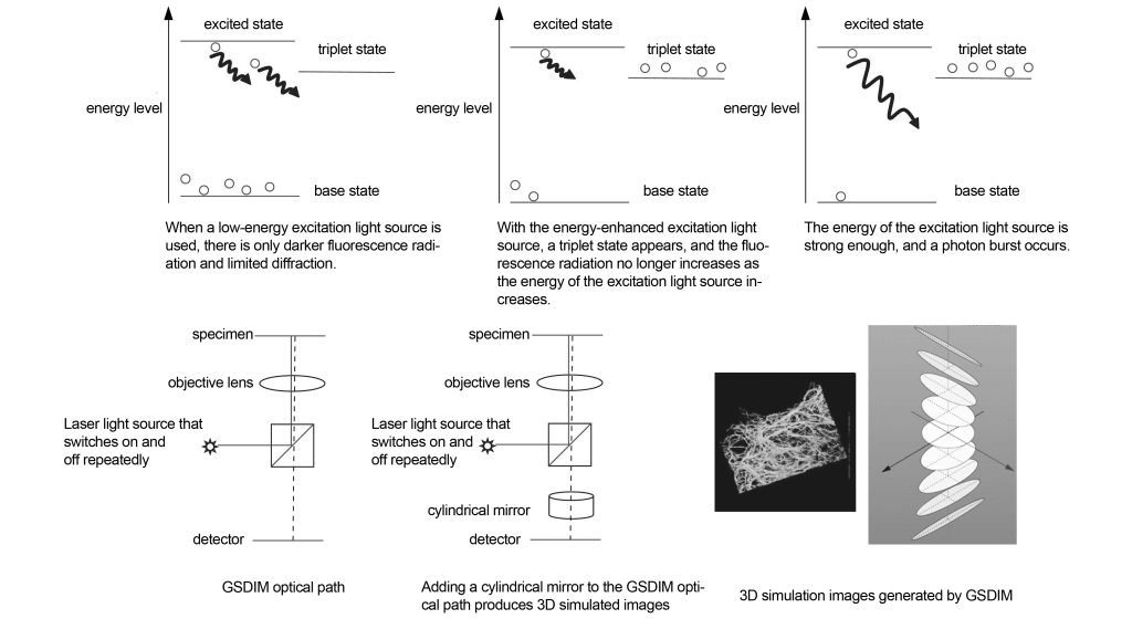
In order to increase the number of electrons that transition from the triplet state to the ground state, thereby speeding up the photon burst time, the specimen can also be irradiated with a second laser beam (405 nm). In GSDIM technology, a strong excitation light source is repeatedly switched on and off, so that the positions where triplet states emit increased fluorescence are random. By recording the positions of these light spots, the GSDIM image of the specimen can be reconstructed.
If a cylindrical mirror is added to the GSDIM optical path, a three-dimensional image can be formed. The cylindrical mirror can control the PSF of the imaging spot according to the imaging position in the three-dimensional image, and then reconstruct the simulated three-dimensional image through the computer.
GSDIM can be used in both confocal and widefield microscopy.
4 Summary
Modern microscopes are based on the brightfield imaging technology of wide-field optical microscopes, which has derived many contrast enhancement foundations (such as phase contrast, DIC, modulation contrast, darkfield, and polarized light), while confocal technology accurately captures the object points on the focal plane. Imaging is essentially a contrast-increasing technology. These techniques are limited by the diffraction limit. Super-resolution technology breaks through the diffraction limit at the molecular level and adjusts the luminescent properties of fluorescent substances through excitation light, thus reducing the luminescent area of the luminescent point.