Basic Principles of Polarizing Microscope
I. Uniaxial and Biaxial Characteristics:
When light passes through a substance, if the properties and path of light do not change with the illumination direction, the substance is optically “isotropic,” also known as uniaxial, such as ordinary gases, liquids, and non-crystalline solids. If light passing through another substance exhibits different properties such as speed, refractive index, absorbance, and the vibrational nature and amplitude of the light waves based on the direction of illumination, the substance is optically “anisotropic,” also known as biaxial, such as crystals and fibers.
II. Polarization Phenomenon of Light:
Based on their vibrational characteristics, light waves can be categorized into natural and polarized light. Natural light has vibrations in many planes perpendicular to the axis of light propagation, with equal amplitude and frequency in each plane. When natural light undergoes reflection, refraction, birefringence, and absorption, it can become light waves vibrating in only one direction, known as “polarized” or “polarized light.”
III. Generation and Function of Polarized Light:
The essential components of a polarizing microscope are the polarizing devices—the polarizer and analyzer. In the past, both were Nicol prisms made of natural calcite. However, due to limitations in obtaining large areas of polarization from large crystal volumes, modern polarizing microscopes use synthetic polarizing mirrors to replace Nicol prisms.
The synthetic polarizing mirror is made of a crystal called quinoline sulfate, also known as Herapathite, and appears olive green. When ordinary light passes through it, it produces linearly polarized light vibrating only along a specific direction.
A polarizing microscope has two polarizing mirrors, one placed between the light source and the specimen called the “polarizer,” and the other placed between the objective and eyepiece called the “analyzer.” These mirrors can be rotated, and their orientations affect the brightness of the field. When the vibrational direction of the polarizer and analyzer is parallel (in the “parallel analyzer position”), the field is brightest. Conversely, when they are perpendicular (in the “crossed analyzer position”), the field is completely dark. If they are inclined, the field shows intermediate brightness.
In the case of a polarizer producing linearly polarized light, if its vibrational direction is parallel to that of the analyzer, light can pass through completely. If it deviates, only a portion passes through, and if it is perpendicular, no light passes through. Therefore, when using a polarizing microscope for examination, the polarizer and analyzer should ideally be in a crossed position.
IV. Birefringent Substance in the Crossed Analyzer Position:
In the crossed position, the field is dark. If the examined object is optically isotropic (uniaxial), regardless of how the stage is rotated, the field remains dark. This is because the vibrational direction of the linearly polarized light from the polarizer does not change and remains perpendicular to the vibrational direction of the analyzer. If the examined object contains birefringent substances, those areas emit light because, after linearly polarized light exits the polarizer and enters the birefringent substance, two linearly polarized lights with mutually perpendicular vibrational directions are produced. When these two lights pass through the analyzer, they may pass through to varying degrees, resulting in a bright image. The vibrational direction of the two polarized lights formed when light passes through a birefringent substance depends on the type of substance.
In the crossed position, when the stage is rotated, the image of the birefringent substance undergoes four changes in brightness within a 360° rotation, with a darkening occurring every 90°. The positions where the vibrational directions of the birefringent substance match those of the polarizer and analyzer are called “extinction positions.” By rotating 45° from an extinction position, the examined object becomes brightest, known as the “diagonal position.” This is because, when deviating by 45°, some of the polarized light reaches the object, decomposes, and some rays can pass through the analyzer, resulting in brightness. Utilizing polarizing microscopy based on these principles allows the determination of isotropic (uniaxial) and anisotropic (birefringent) substances.
V. Interference Colors:
In the crossed analyzer position, observing birefringent substances with mixed light of various wavelengths as the light source, colors appear in addition to the brightest diagonal position as the stage is rotated. The appearance of colors is mainly due to interference colors (although the color of the examined object itself can also contribute). The distribution characteristics of interference colors depend on the type of birefringent substance and its thickness. Interference colors are caused by the dependency of the delay on the wavelength of light for different regions of the examined object. If the delay in one region differs from that in another region, the color of the transmitted light through the analyzer also differs.
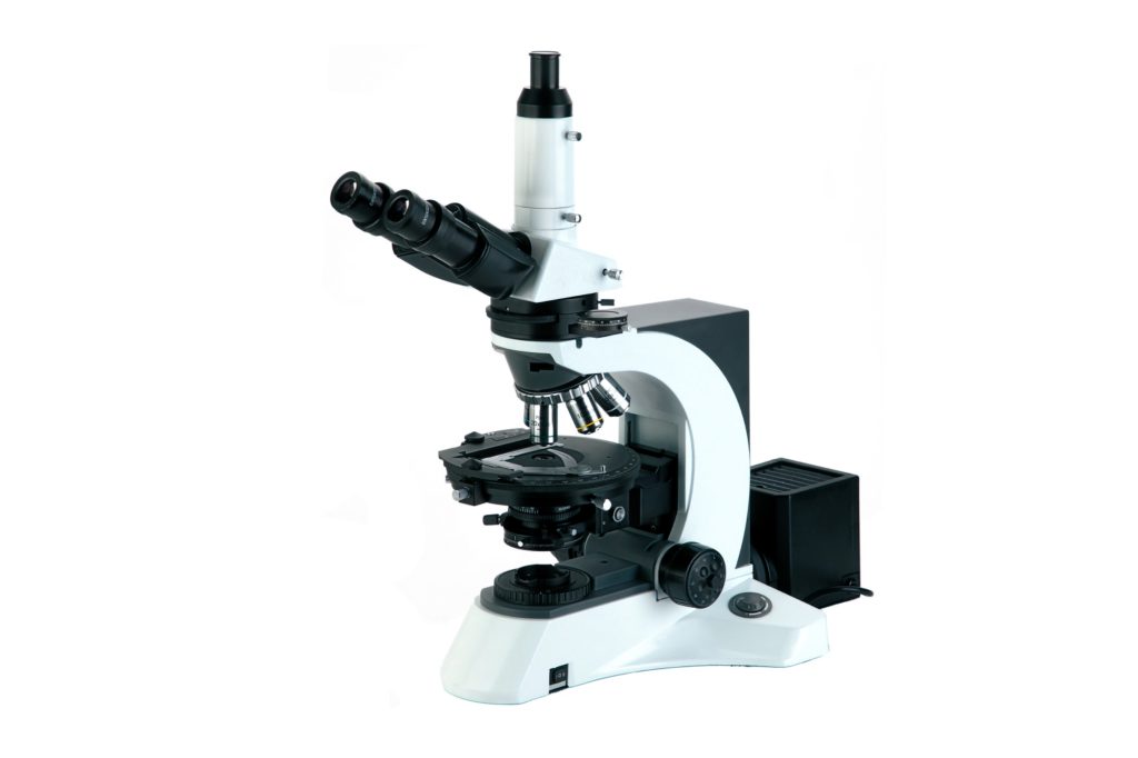
Performance of NP-800M Polarizing Microscope
- Specialized strain-free objectives provide high-definition, high-contrast images.
- Used for various observations such as single polarized light, positive imaging mirror inspection, cone light mirror inspection, etc.
- Three main illumination modes: transmission, reflection, and trans-reflection, with a 24V/100W long-life halogen light source.
- The platform can be positioned at 45° and equipped with a polarizing-specific large-range movable scale. There is no interference phenomenon when changing magnification objectives, greatly improving work efficiency.
- Professional polarizing microscopes are used in geology, petroleum, chemical, polymer, liquid crystal, and other fields.
Technical specifications of the NP-800M Polarizing Microscope.
| Optical System | Infinite optical system |
| Viewing Head | Seidentopf trinocular head inclined at 30°, Interpupillary 48-75mm |
| Eyepiece | Plan eyepiece EW10X/22 |
| Plan eyepiece with scale of crosshair,Plan eyepiece with cross,.Plan eyepiece with gridding | |
| Strain-Free Plan Achromatic Objective | 4X/0.10/∞/- WD 17.3mm |
| 10X/0.25/∞/0.17 WD 10.0mm | |
| 20X/0.40/∞/0.17 WD 5.10mm | |
| 40X/0.65/∞/0.17 WD 0.54mm | |
| 100X/1.25/∞/0.17 WD 0.13mm | |
| Nosepiece | Backward quintuple nosepiece, Center adjustable |
| Analyzer | 360° dial rotation Minimum scale reading: 0.1° (Vernier scale) |
| Conoscopic observation | Switch between orthoscopic and conoscopic observation, Bertrand lens position adjustable |
| Optical Compensator | First-order red plate, Guarter-wave plate, Quartz wedge |
| Polarizing Rotatable Stage | Diameter Φ170mm, Center adjustment, 360° scale, Minimum division 1°, Minimum reading 6′ by means of vernier scale, 45° Click stop knob |
| Attachable Stage | Moving range 30mmX40mm |
| Condenser | Strain-free swing condenser NA0.9/0.25 |
| Focusing | Coaxial coarse & fine adjustment, Range 32mm, Fine division 0.001mm, Coarse stroke 37.7mm per rotation, Fine stroke 0.1mm per rotation |
| Polarizer | 360° rotatable 0°position adjustable |
| Illumination | 4V/100W Halogen lamp, Brightness adjustable |
| Filter | Blue filter Φ 45mm |
| ND6 Neutral density filter Φ 45mm | |
| ND25 Neutral density filter Ф45mm | |
| Attachment | Video attachment |
| 0.01mm Micrometer |