Ⅰ Main components and optical path diagram of industrial measurement microscope
Industrial measuring microscopes are widely used in many industries, especially in the electronics industry. It is a “powerful” instrument for observing the structure of circuit boards and accurately measuring distances. Today I will briefly talk with you about the basic knowledge of microscope measurement and related terminology.
Let’s start with the main components and optical path diagram of the microscope.
Main components and optical path diagram
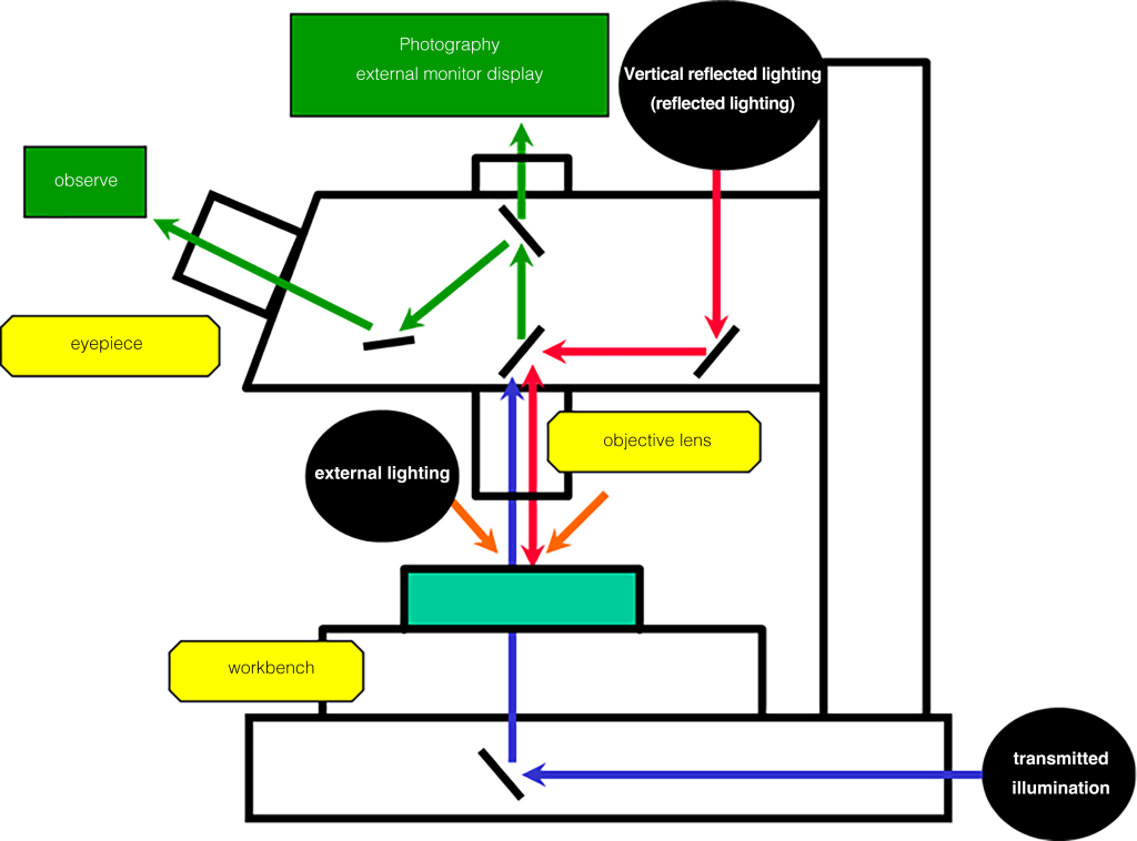
Ⅱ Lighting method
In the picture above, three illumination methods of the microscope are mentioned. The observation imaging is different according to different lighting methods, so it is necessary to choose the most suitable lighting method according to different workpieces and measurement parts.
01 Transillumination
Transillumination is a method of observing through contour light, especially when observing the measurement contour. The edges are clear and easy to observe.
02 Vertical reflected lighting
Vertical reflected illumination is a vertical illumination measurement of the surface of the workpiece, suitable for observation and measurement of surface properties.
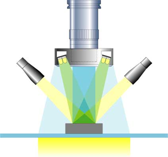
03 Exterior lighting
(Ring fiber · Ring LED · Dual fiber)
External lighting uses oblique light to illuminate the surface of the measurement workpiece, enabling three-dimensional observation with good color repeatability.
When using a microscope, you may come across professional terminology for microscopy. What do these terms mean?
Ⅲ Professional terms for industrial measurement microscopes
Overview of professional terminology
01 Comprehensive magnification
Comprehensive magnification = eyepiece magnification x objective lens magnification.
Example: When using a combination of 10x eyepiece and 100x objective lens, the comprehensive magnification of the observed image = 10 x 100 = 1000x.
02 Field number (F.N)
The field of view number refers to an indicator of whether the eyepiece can observe in a wide field of view. The observation range of the sample surface depends on the field diaphragm diameter of the eyepiece, and the value of this diameter (in mm) is called the field number. F.N=Field Number.
When equipped with a 1x objective lens, the diameter of the image observed through the eyepiece is 24mm
03 Field of view (FOV)
Refers to the actual scope of viewing and observing the workpiece when looking through the eyepiece.
The light that passes through the objective lens and imaging lens is imaged on the reticle (focus position of the imaging lens), and the image magnified by the eyepiece is observed.
04 PC display magnification (TV comprehensive magnification)
PC monitor magnification (TV comprehensive magnification) refers to the ratio of the diagonal length of the camera imaging element to the diagonal length of the PC monitor screen. When the microscope is connected to a computer through a CCD device for imaging observation, the display magnification needs to be evaluated.
The calculation formula for PC monitor magnification (TV comprehensive magnification) is as follows:
For example: The comprehensive TV magnification using a 10× objective lens, a 2/3-inch CCD camera, and a 17-inch monitor is 10 × 39.3 = 393 × (approximately 400 times)
05 Working distance (WD)
The working distance refers to the distance from the objective lens head’s apex to the inspection object’s surface when focusing. Clear focus can be achieved at this distance. The longer the working distance, the better the operability when focusing, and there is no need to worry about the lens hitting the inspection object.
Schematic diagram of working distance
06 Par field distance (PFD)
The parfocal distance refers to the distance from the installation position of the objective lens when focusing to the surface of the inspected object when focusing.
The magnification is different, but the distance from the objective lens’s mounting surface to the inspection object’s surface remains unchanged, so there is no need to refocus when changing magnification.
07 Focus distance (FD)
Focal distance refers to the distance from the lens (principal point) to the focal point. FD: Focus Distance
08 Depth of focus (DOF)
Focus depth refers to the range of forward and backward movement that can be observed after focusing.
The higher the magnification of a high-magnification lens, the deeper and shallower it is (short)
The lower the magnification of a low-magnification lens, the deeper it is (longer)
Observation below the resolution of the human eye (about 0.1 to 0.3mm) requires the use of a microscope. What are the observation methods with a microscope?
Ⅳ Observation methods with industrial measuring microscopes
- Bright-field observation
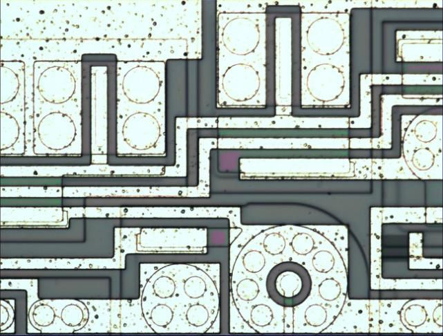
Vertically illuminates the surface of the measurement object, suitable for surface observation of metal, printed circuit boards, and shallow holes.
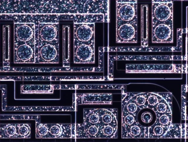
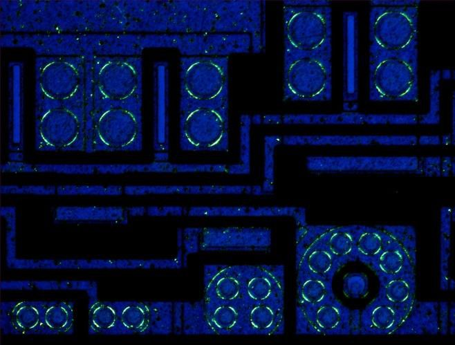
- Darkfield observation
By observing the scattered light emitted from the workpiece, scratches, dust, and unevenness that cannot be observed in bright fields can be completed, and low-reflection workpieces can be observed competently.
- Polarized observation
Observing substances with polarizing properties, suitable for surface observation of semiconductor materials, liquid crystals, crystals, metal structures, minerals, etc.
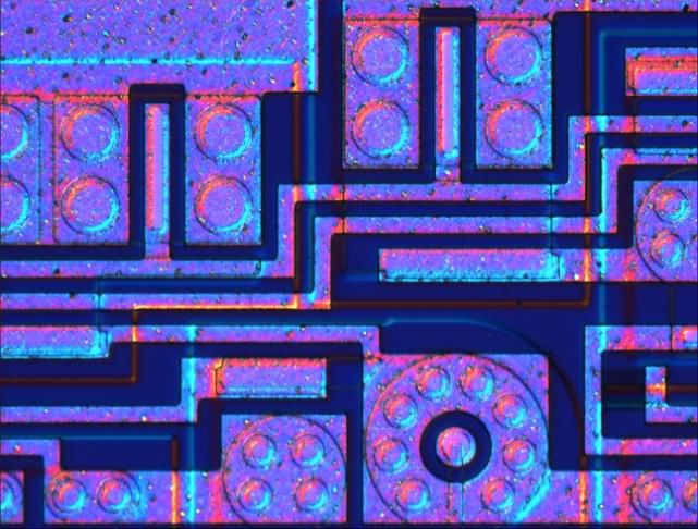
- Differential interference (DIC) observation
The Nomarski prism is used to divide the light into two beams, resulting in changes in light shade and contrast, allowing for three-dimensional observation. It is suitable for observing crystal defects of silicon wafers, damage inspection of magnetic head grinding surfaces, painted surfaces, metal structures, ore surfaces, etc.
Ⅴ NX series industrial inspection microscope
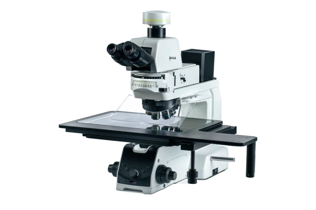
Whether it is a very small sensor, a large wafer, or even an entire LCD, it can be observed with the NX series industrial inspection microscope. It has various sizes of loading platforms and a large moving range, and can move and focus quickly and easily, and quickly locate the sample range. It is an ideal tool for microscopic observation of large-area industrial samples.
Ⅵ Advantages of NX series industrial inspection microscopes
- Accurate imaging and high color reproduction – the NIS45 infinity optical system, has excellent optical qualities such as long working distance, strong chromatic aberration correction ability, and sharp imaging.
- Designed specifically for industrial large-area observation needs – using a 12-inch ultra-large stage to meet FPD and LSI detection; at the same time, humanized components such as clutch platform handles and objective lens conversion are added, which greatly reduces the risk of long-term microscopic operations of fatigue.
- Modular design to achieve diversity of observation methods – using modular design, it can realize bright field, dark field, differential interference, fluorescence, polarization, and other observation methods; it is suitable for semiconductor devices, FPD, electronic devices, materials, precision mold manufacturing, etc. Ideal tool for quality control and research.