Introduction:
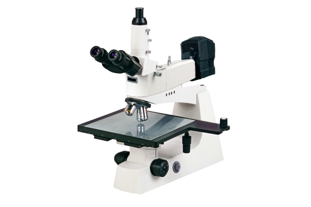
Industrial measurement microscopes find extensive applications across various industries, particularly in the electronics sector, where they serve as indispensable tools for observing circuit board structures and precisely measuring distances. Today, we will delve into the fundamental knowledge and relevant terminology related to measurement using microscopes.
Main Components and Optical Diagram:
I. Illumination Methods:
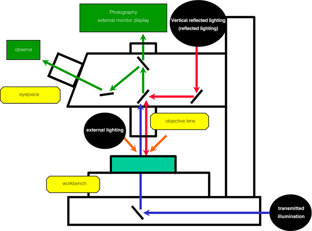
In the diagram, three illumination methods for microscopes are mentioned. The choice of illumination method affects observation and imaging differently, necessitating the selection of the most suitable method based on the workpiece and measurement location.
01 Transmitted Illumination:
Utilizes transmitted light to observe contours, which is especially useful for observing and measuring contours with clear and distinct edges.
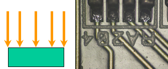
02 Vertical Reflective Illumination:
Illuminates the surface of the measured object vertically, suitable for observing and measuring surface characteristics.
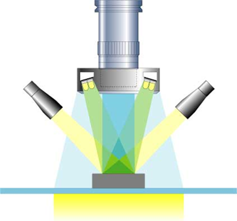
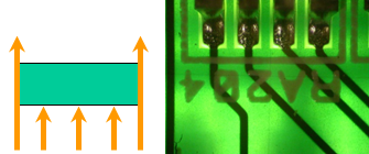
03 External Illumination:
(Ring Fiber Optics, Ring LED, Dual Fiber Optics)
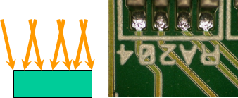
Uses oblique light to illuminate the surface of the measured object, enabling three-dimensional observation with excellent color reproducibility.
II. Professional Terminology:
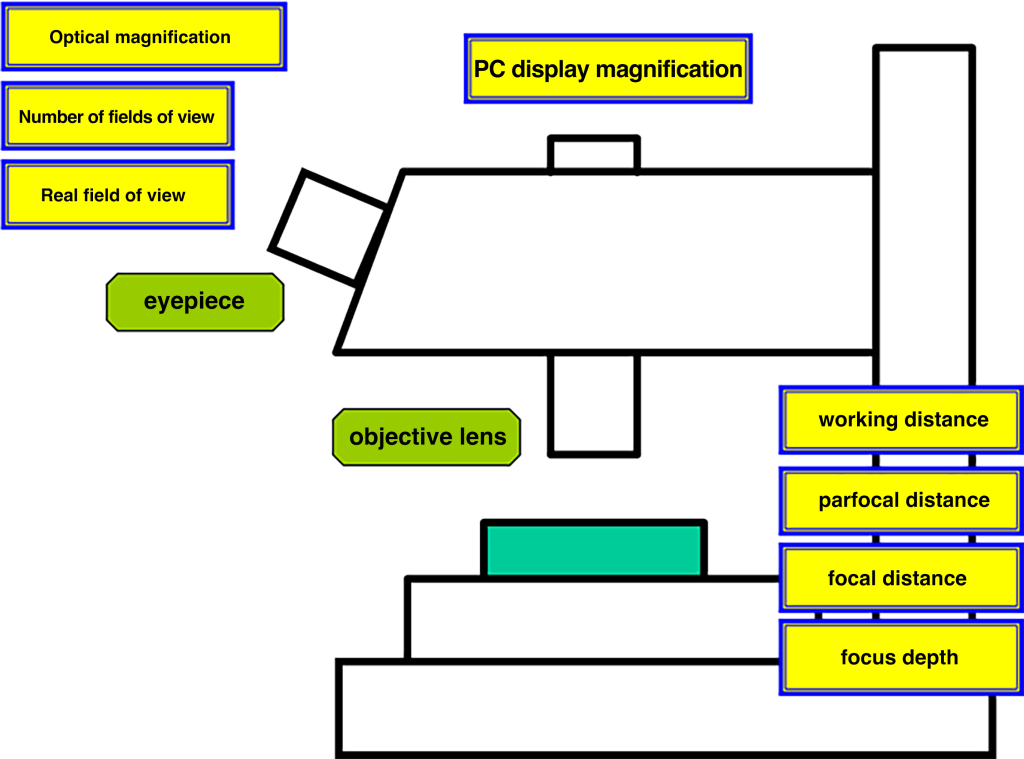
Comprehensive Magnification:
Comprehensive magnification = Eyepiece magnification x Objective magnification.
Example: Using a 10x eyepiece and a 100x objective, the comprehensive magnification = 10 x 100 = 1000x.
Field Number (F.N):
Indicates whether the eyepiece can be observed under a wide field of view. The observed range on the sample surface depends on the eyepiece’s field number, measured in millimeters, known as Field Number (F.N).
When using a 1x objective, the observed image diameter through the eyepiece is 24mm.
Field of View (FOV):
Refers to the actual observation range when examining the workpiece through the eyepiece.
FOV = Eyepiece field number / Objective magnification
PC Display Magnification (TV Magnification):
The ratio of the diagonal length of the camera’s image sensor to the diagonal length of the PC display screen. When imaging with a microscope connected to a computer via a CCD device, the display magnification needs to be evaluated.
TV Magnification = Objective magnification × (Display screen diagonal length / CCD camera image sensor diagonal length)
Working Distance (WD):
The distance from the top of the objective lens head to the surface of the inspected object during focusing, ensuring clear focus. Longer working distances enhance operational ease during focusing.
Par Field Distance (PFD):
The distance from the installation position of the objective lens to the surface of the inspected object when focused.
Focus Distance (FD):
The distance from the lens (principal point) to the focus.
Depth of Focus (DOF):
Refers to the range in which the image remains clear while moving the focus position after focusing.
DOF: Depth Of Focus
Depth is shallower for higher magnification lenses and deeper for lower magnification lenses.
III. Observation Methods:
- Bright Field Observation:
Vertical illumination for measuring the surface of objects, suitable for observing metal, printed circuit boards, and shallow holes.
- Dark Field Observation:
Observing scattered light from the workpiece is useful for observing scratches, dust, and irregularities not visible in bright fields, and it is suitable for low-reflective workpieces.
- Polarized Observation:
Observing substances with polarizing characteristics, applicable to surface observation of semiconductor materials, liquid crystals, crystals, metal structures, and mineral surfaces.
- Differential Interference Contrast (DIC) Observation:
Using Nomarski prisms to split light into two beams, creating brightness and contrast variations for stereoscopic observation. Suitable for examining crystal defects in silicon wafers, damage inspection of magnetic head grinding surfaces, coating surfaces, metal structures, and ore surfaces.