The illumination system is a typical example of a non-imaging optical system and an important part of an optical instrument. Generally speaking, all optical systems whose research objects are non-luminous objects must be equipped with lighting devices, such as microscopes, projection systems, machine vision systems, industrial lighting systems, etc.
Microscopes mostly work under high magnification, so lighting is needed to provide sufficient brightness to ensure the illumination of the image plane, and at the same time ensure the uniformity of the illumination of the image plane.
The lighting system usually includes a light source, a condenser and other auxiliary lenses and reflectors. Among them, the brightness, light-emitting area, and uniformity of the light source determine the form that the spotlight lighting system can adopt. Light sources that can be used in the lighting system include tungsten-halogen lamps, metal halide lamps, high-pressure mercury lamps, light-emitting diodes (LEDs), xenon lamps, and arc lamps. Some light sources have sufficient brightness and uniformity in their light-emitting surface, and can be used for direct lighting. Minimal energy loss, These two aspects are common problems that need to be solved when designing different lighting systems.
The illumination optical system focuses on the distribution of energy rather than the transmission of information. The concern is not the imaging quality on the image plane, but the distribution and size of the illumination on the illuminated surface.
1 lighting method
1.1 Illumination of transparent objects
For transparent specimens can be illuminated with transmitted light. There are two methods of transmitted lighting:
(1) Critical lighting
This kind of lighting requires that the light source image formed by the condenser mirror coincides with the object plane of the observed object, as shown in Figure 1, which is equivalent to placing a light source on the object surface, and the shape of the filament appears on the image surface at the same time, resulting in unsatisfactory observation Effect.
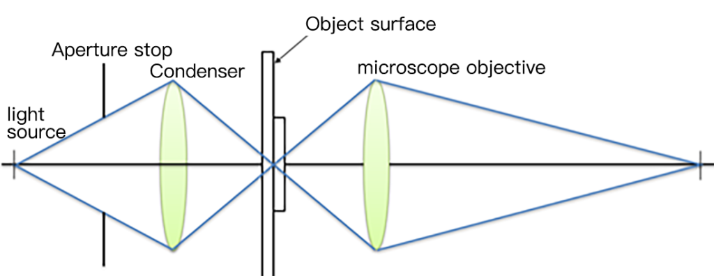
In transmitted illumination, in order to make full use of the aperture angle of the objective lens, the condenser lens should have the same or slightly larger numerical aperture as the objective lens. The aperture diaphragm of the critical illumination condenser is always set on the objective focal plane of the condenser. If the microscope uses a telecentric objective, the exit pupil of the condenser coincides with the entrance pupil of the objective. The diaphragm of the condenser is made into a variable diaphragm, which can arbitrarily change the aperture angle of the incident condenser to match the numerical aperture of the objective lens. Since the exit pupil and image-side field of view of the critical illumination condenser coincide with the entrance pupil and object-side field of view of the objective lens respectively, a light pipe of “pupil to pupil, field of view to field of view” is formed.
- Disadvantages of critical lighting
The reason is that when the brightness of the light source is not uniform or presents an obvious filament structure, it will be reflected on the object surface, making the object surface illuminance uneven, thus affecting the observation effect. In order to achieve relatively uniform illumination, this illumination method requires high uniformity of the illuminant itself, and at the same time requires sufficient defocus between the surface of the illuminated object and the image of the light source. The aperture angle of the follow-up objective lens should be larger. If the aperture angle of the objective lens is too small, the depth of focus will be large, which will easily reflect the inhomogeneity of the illuminant itself.
(2) Kohler lighting
The Kohler illumination optical system is shown in Fig. 2. The light source is imaged on the field diaphragm of the illumination system through the front group of the condenser; the front group of the condenser is imaged on the specimen through the rear group of the condenser, and at the same time the field diaphragm of the illumination system is imaged at infinity, making it consistent with the telecentric objective lens The entrance pupils coincide.
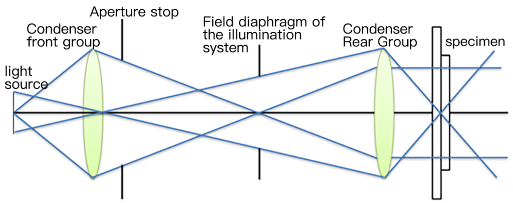
The front group of condensers in Koehler illumination is called Kohler mirror, which gets the uniform illumination of the light source, and forms an image on the specimen after passing through the condenser. Therefore, uniform illumination is obtained on the specimen, which is an important feature of Koehler illumination. The aperture diaphragm in the condenser is close to the front group of the condenser, and the image formed by the rear group of the condenser, that is, the exit pupil of the condenser is also close to the object plane (specimen) of the microscope, so the diaphragm plays a role in limiting the field of view of the microscope. The exit pupil and image-side field of view of the Kohler illumination condenser system coincide with the object-side field of view and entrance pupil of the microscope respectively, thus forming a “field-to-pupil, pupil-to-field” light pipe.
1.2 Illumination of opaque objects
For opaque objects, use the method of lighting from the side or from above. At this point, the specimen is imaged by scattered or reflected light.
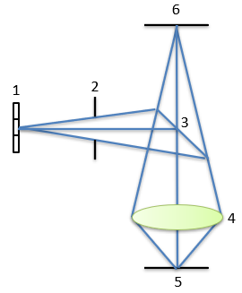
Side illumination is to place the light source obliquely above the specimen. Some microscopes use small light bulbs around the objective lens to form oblique illumination. The upper illumination method makes the objective lens double as a condenser, as shown in Figure 3. The light emitted by light source 1 is projected onto the half mirror 3 through diaphragm 2, and the reflected light is directed from the objective lens 4 to the object plane 5, and then the diffusely reflected light from the object plane 5 is imaged on the image plane 6 through the objective lens 4 .
2. Dark field illumination method
Darkfield illumination is suitable for observation of discretely distributed particle specimens. To some extent, darkfield illumination can improve the resolution of the microscope.
The principle of dark field illumination is to prevent the light passing through the specimen from entering the objective lens directly, and only allow the light scattered by the particles to enter the objective lens. In this way, the image surface formed by the objective lens is a scene in which bright particles are distributed on a dark background. Due to the good contrast (contrast), it is beneficial to the resolution of particles.
Darkfield illumination is divided into one-way dark field illumination and two-way dark field illumination.
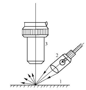
2.1 One-way dark field illumination
Fig. 4 is a schematic diagram of unidirectional dark field illumination. After the light emitted by the illuminator 2 is reflected by the opaque specimen 1, only the scattered light enters the objective lens for imaging. This lighting method is effective for observing the existence and movement of particles, but there is a phenomenon of “distortion” in the reproduction of object details.
2.2 Two-way dark field illumination
The optical structure of two-way dark field illumination is shown in Fig. 5. Immerse oil between the last piece of the condenser and the objective glass.
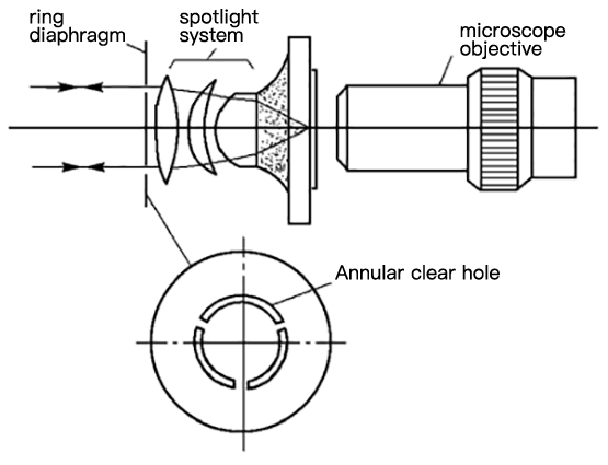
In front of the three-lens condenser, a ring diaphragm is placed, and the diameter of the position of the ring diaphragm needs to be designed according to the following imaging relationship: when there is no immersion liquid between the cover glass and the objective lens, the light emitted from the aperture The light beam illuminates the specimen under the cover glass before entering the cover glass, then enters the cover glass, and is totally reflected from the cover glass. What enters the objective is only light scattered by particles on the specimen, creating darkfield illumination. This kind of lighting belongs to symmetrical lighting, which eliminates the distortion of unidirectional dark field lighting to a certain extent.
3. Condenser
In the illumination system, the function of the condenser lens is to gather the light to the greatest extent and project it into the imaging system of the microscope.

In Fig. 6, when the light source 1 is used to illuminate object 3, if the condenser lens 2 is not added, the light irradiating the specimen is limited to angle 2Us. After adding condenser lens 2, the angle increases to 2UB. At this time, the light energy entering the optical system increases sharply according to the square relationship of the increase ratio of the angle.
Based on the function of the condenser, the requirements for the quality of the condenser are limited to spherical aberration and chromatic aberration, so as to adapt to the aberration of the microscope objective lens.
3.1 Chromatic difference
Generally, in the design, only the minimum value can be obtained under the possible conditions, so the material selection of the condenser is very important. The material of the condenser lens should be low dispersion optical glass (such as K9 glass). As the result of superposition of positional chromatic aberration in the field of view is a color phenomenon at its edge, as long as the illuminated area is larger than the size of the specimen, the influence of chromatic aberration can be avoided.
However, for Kohler illumination, the condenser is required to image its diaphragm on the object surface, and the effect of chromatic aberration is avoided, and the solution of an achromatic condenser is replaced.
The structure of the achromatic condenser is similar to that of a high-power microscope objective, except that the focal length is longer so that the light beam can pass through a thicker object glass (about 2mm) to illuminate the specimen.
3.2 Spherical aberration
The existence of spherical aberration will affect the ability of the condenser to gather light and reduce the lighting effect. The correction tolerance of spherical aberration is usually expressed by the ratio K of the smallest diffuse spot of the point source to the light source:

In the formula, z`min is the minimum diffuse spot diameter produced by the concentrating system for the point source; β is the magnification of the concentrating system; D is the size of the light source. The lighting system of projection equipment requires K=3%~10%; for general microscopes, K=20%~30%.
Since the structure of the condenser is mainly a convex lens with light-gathering ability, the key to reducing spherical aberration is whether the focal length of each lens is reasonable. u said.
Experience has proved that in order to prevent the spherical aberration of the condenser system from being too large, the relationship between the number of lenses used in the condenser and the deflection angle Δu they can bear is shown in Figure 7.
| Piece | 1 | 2 | 3 |
| Angle Δu | 0.2~0.3 | 0.3~0.6 | 0.6~0.9 |
3.2 Common structural forms of condensers
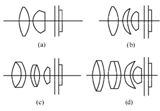
- (1) The two-piece type is shown in Figure 8(a), the acceptable numerical aperture is 0.8, and its value is 1.2 when immersed in liquid.
- (2) As shown in Figure 8(b) of the three-piece type, the acceptable numerical aperture is 0.9, and its value can reach 1.4 when immersed in liquid.
- (3) The five-chip system is shown in Figure 8(c). There are two glued groups and a hemispherical lens in the system, so it can meet the requirements of aplanatic, chromatic and sinusoidal correction, and the affordable numerical aperture is 0.9.
- (4) The six-piece type is shown in Figure 8(d), which is used for high-power microscopes, and the numerical aperture can reach 1.4 when immersed in liquid.
Figure 8(c) and Figure 8(d) show the structures of two achromatic condensers, which are the same as the Amici objective and the Abbe objective, but the difference is that the focal length is longer and the achromatization is not as strict as that of the microscope.