1. Introduction to Optical Imaging Technology
Studying the properties of materials with optical methods is an extremely old research method. The development of microscope technology has made it possible to study the microstructure of materials with optical methods.
Current optical imaging technologies mainly include fluorescence and bioluminescence. Fluorescence imaging technology commonly uses GFP, RFP and near-infrared (NIR) fluorescein genes as reporter genes.
Bioluminescence imaging technology mainly includes two types of reporter genes: luciferase gene and Renilla luciferase gene, and the substrates are luciferin and coelenterazine respectively.
With the development of optical imaging technology, more sophisticated microscopes provide convenience for us to study the interaction between structures and light at a more microscopic level. Polarizing microscopes, PolScope microscopes, etc. can observe polarization properties that cannot be directly captured by the naked eye, thus providing a powerful tool for revealing structural information inside the crystal.
2. Two types of optical microscopes
NO.1 Polarized microscope
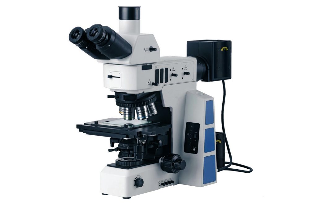
The polarizing microscope is the most basic optical equipment in polymer crystallization research.
Polymer crystals have birefringent properties due to the orderly orientation and close packing of molecular chains. The polarizing microscope uses a set of polarizing plates with polarization directions perpendicular to each other (orthogonal) to analyze the optical path difference of two polarized lights propagating along the direction of the maximum principal refractive index and the direction of the minimum principal refractive index of the electrical vector vibration direction in the polymer crystal. , reflected as the light intensity of the image.
Polarizing microscope application cases
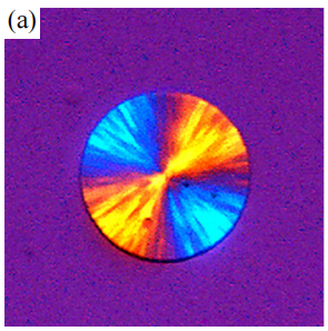
Positive and negative spherulites: Through a polarizing microscope with a first-level red compensator, the positive or negative nature of the spherulites can be judged, that is, the maximum refractive index is radial or tangential.
The direction of the maximum refractive index of negative spherulite is along the tangential direction of the spherulite. Since the polyethylene molecular chain itself lacks any polar side groups, the side direction can only provide van der Waals forces. Therefore, for polyethylene crystals, the direction with the largest refractive index should be along the direction of the molecular chain. Based on this, Keller proposed that the direction of the molecular chains in polyethylene spherulites is also arranged along the tangential direction of the spherulites.
However, for polymers containing polar groups such as poly(R-3-hydroxybutyrate) (P3HB), due to the strong hydrogen bond polarization perpendicular to the direction of its molecular chain, the direction of the maximum refractive index is perpendicular to the direction of the molecular chain. , so it appears as positive spherulites, or depending on the crystallization conditions, both positive and negative spherulites can be obtained.
- (a) Picture: The negative spherulite of the polylactic acid stereocomplex crystallizes at 160°C. The first and third quadrants are yellow, and the second and fourth quadrants are blue.
- (b) Picture: poly(R-3-hydroxybutyrate) spherulite crystallizes at 50°C. The first and third quadrants are blue, and the second and fourth quadrants are yellow. The scale bar is 50 μm.
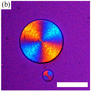
NO.2 PolScope microscope
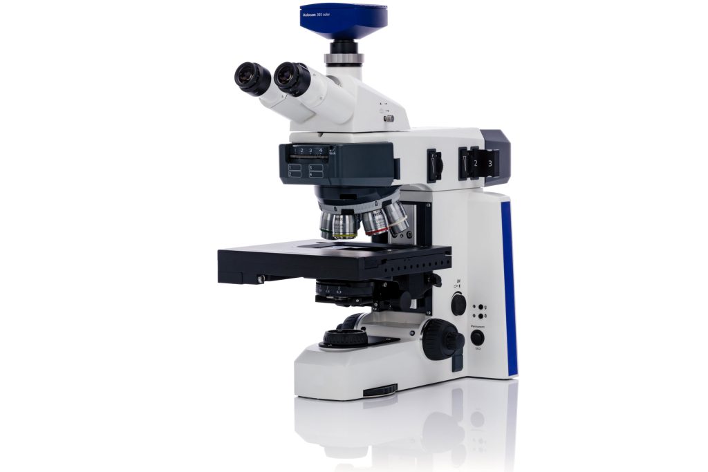
As mentioned before, the image obtained by an ordinary polarizing microscope can only reflect the final light intensity of birefringence synthesis, and cannot separately obtain the optical axis azimuth angle of the sample and the optical path difference caused by birefringence.
Oldenbourg and Mei et al. developed the PolScope system to obtain these two parameters. By changing the polarization direction and phase angle of the polarizer and obtaining the light intensity distribution of the sample image at several different angles, the optical path difference and slow axis (corresponding to the maximum refractive index) direction on each pixel can be analyzed.
PolScope system application cases
Polscope can quantitatively measure the maximum refractive index direction of linear birefringence and the corresponding phase difference. With this technology, the molecular orientation structure in various materials can be analyzed. Especially in polymer crystals, the direction of the maximum refractive index is often closely related to the direction of the molecular chain. Therefore, PolScope can provide important help in analyzing the orientation structure of polymer crystals.
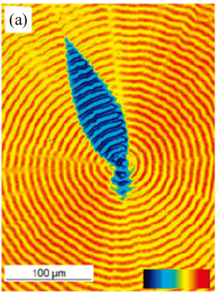
Xu Jun et al. observed that the spherulite structure of chiral poly(R-3-hydroxyvalerate) (PHV) isothermally crystallized has a special “eye-like region” that is different from the ordinary spherulite structure, as shown in Figure (a) ( b)(c).
- (a) The magnitude of the birefringent retardation, shown in false color, with red indicating a retardation of 273 nm and black indicating zero birefringence.
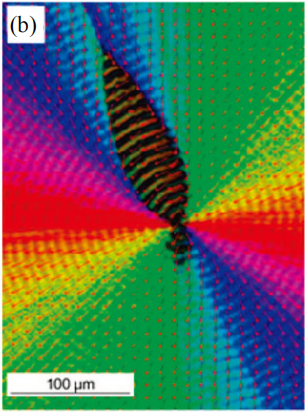
- (b) The direction of the slow optical axis at each position, usually represented by short lines every 15 pixels in the horizontal and vertical directions of the original video frame.
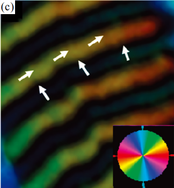
- (c) Magnified photomicrograph of the eye-like region, pseudocolor indicates the azimuth of the slow optical axis at each pixel, and white arrows indicate the direction of the slow optical axis in the band.
Using the PolScope system for characterization, it was found that in the ordinary spherulite area, the direction of the maximum refractive index is always along the radial direction, while in the “eye” area, the direction of the maximum refractive index of the crystal shows periodic alternation, along the radial and circumferential directions of the spherulite.
Therefore, it shows annular bands with alternating positive and negative properties under polarized light. This indicates that the lamellae in PHV spherulites are twisted along two crystallographic axes. The unit cell of PHV is the P212121 orthorhombic crystal system, and the directions of the three crystal axes correspond to three different principal refractive indexes. The crystal is an optical biaxial crystal with two optical axis directions.
3 Summary and Outlook
The development of optical microscopy technology provides us with intuitive and convenient help in studying micron-scale polymer structures. Polymer crystals have unique optical properties due to optical anisotropy caused by orientation. The interaction between polarized light and crystals provides a wealth of information for the analysis of crystal structures.
In addition to the two optical characterization methods introduced in this article, there is also fluorescence super-resolution microscopy that can break through the optical resolution limit caused by wavelength, down to the scale of tens of nanometers. Confocal microscopy can break away from the two-dimensional limitations of optical imaging and assist in establishing the characteristics of the three-dimensional structure of materials.
According to the needs of the sample, rational selection of the optical imaging method used can provide us with great help in intuitively understanding the internal microstructure of polymer materials and the crystallization behavior of polymers. It should be pointed out that due to the limitation of the wavelength of light, the smallest scale that an optical microscope can resolve is generally a few hundred nanometers, making it difficult to observe nanostructure information of lamellae or smaller scales. In order to obtain smaller-scale structural information, atomic force microscopy, scanning electron microscopy, and transmission electron microscopy can be further combined for characterization.