As we all know, metallographic microscopes have different observation modes such as bright field, dark field, polarized light, and differential interference. In the process of observing metallographic structures, the most widely used method is bright field, and most metallographic inspections can be shot in bright field mode. However, darkfield, polarized light and differential interference have their unique roles in materials analysis.
First, let’s look at how different functions are implemented through principles.
1. Principles of different field-of-view functions of metallographic microscopes
(1) Bright-field principle
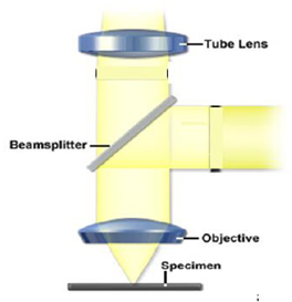
The spectroscope is made of flat glass, and the light beam illuminates the surface of the sample vertically. The image is clear and flat, and can truly display various tissues, but it lacks a three-dimensional sense.
(2) Dark field principle
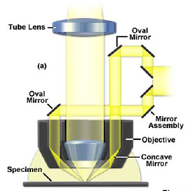
The incident light forms an annular beam after passing through the reflector assembly, irradiates the curved reflector, and reflects to the sample surface at a very large inclination angle. If the surface of the sample is flat, you will see darkness. The uneven tissue will cause diffuse reflection of light, and only then will a bright image be displayed.
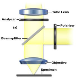
(3) Polarized field of view principle
Add a polarizer to the incident light path and the observation tube. When the two polarizers are in an orthogonal position, the isotropic metal disappears, and the anisotropic metal turns the reflected light into elliptically polarized light, showing a different Contrast between light and dark.
(4) Differential interference field of view principle
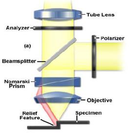
Based on the polarizing component, a Normarski prism is added to make use of the tiny height difference on the surface of the sample to improve the contrast between tissue details through the interference of light, giving the image a sense of relief and low requirements for sample preparation. Some samples only need Polished, no corrosion is required.
Note: Figures 1 to 4 are derived from Zeiss metallographic microscope display documents.
2. Application of different field-of-view functions of metallographic microscope
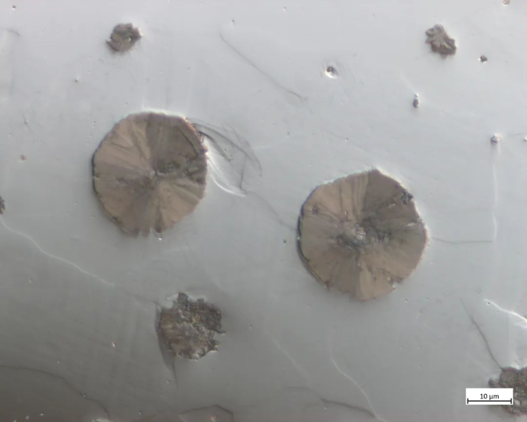
After understanding the principles of different observation modes, we can demonstrate the characteristics of different fields of view by using the spheroidal graphite in ductile iron to produce different imaging phenomena in different fields of view. By polishing the ductile iron sample without corrosion, the observation results in different fields of view can be obtained, as shown in Figures 5 to 8. Under a bright field, it can be seen that the surfaces of the graphite balls and the matrix structure are flat, with no obvious scratches (Figure 5). In the same picture, small scratches can be seen under a dark field, and the internal structure of the graphite balls is clear (Figure 6). Under the cross-polarized field of view, you can see the typical “black cross” phenomenon of graphite spheres (Figure 7). By adding differential interference based on polarization, you can see that the graphite spheres and the grains with different orientations in the matrix all show a Relief feeling (Figure 8)
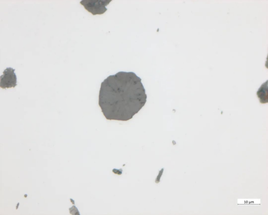
Spherical graphite (polished state)
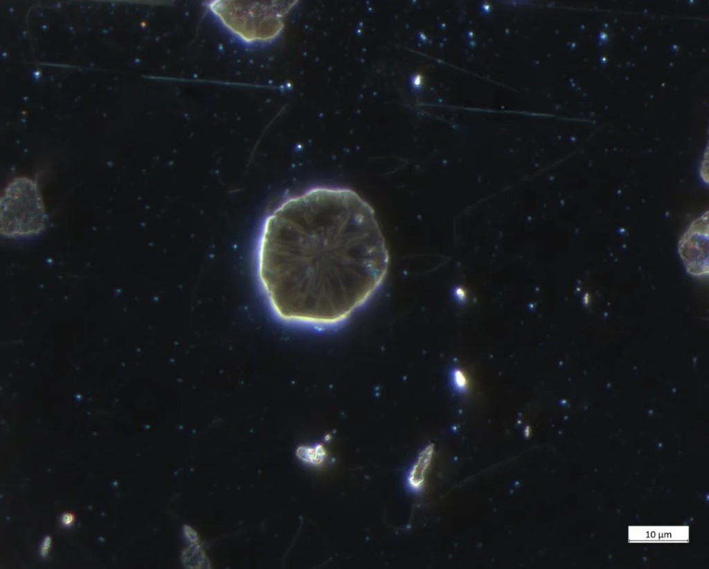
The internal structure of graphite balls is clear
(Polished state)
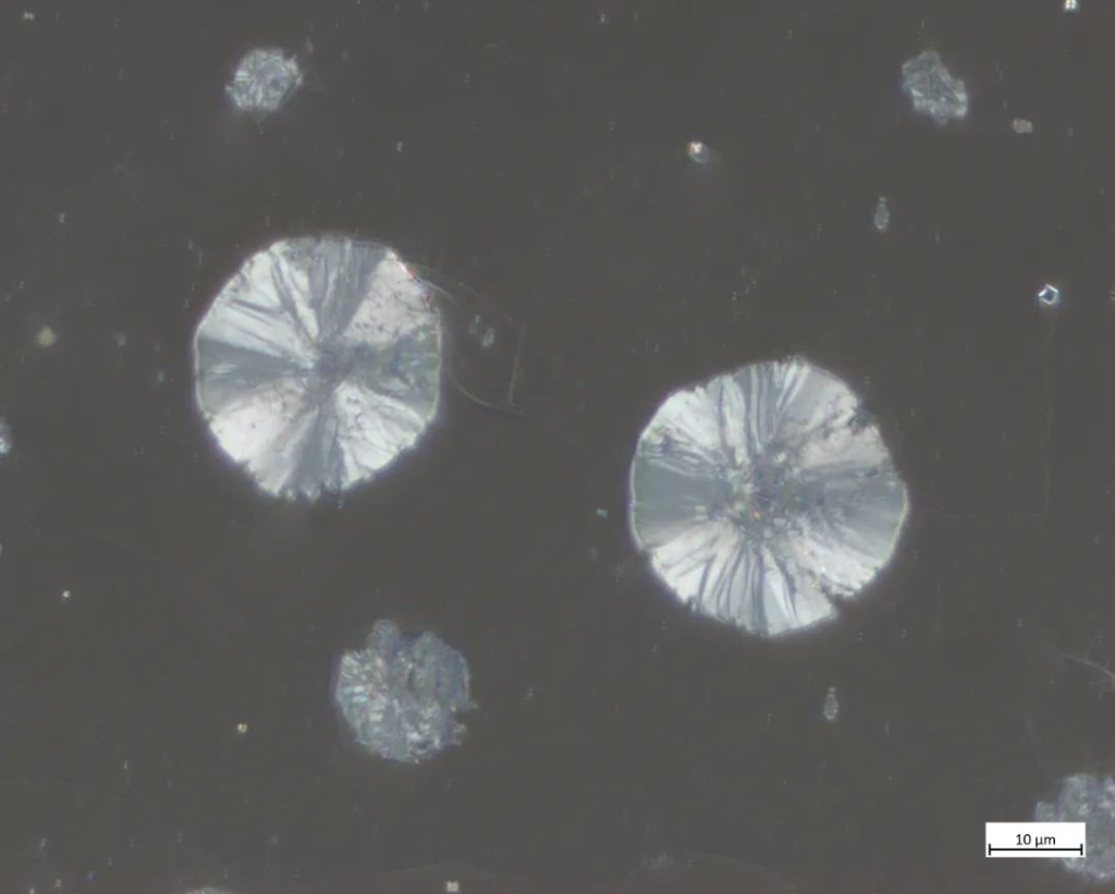
Typical “black cross” phenomenon
(Polished state)
Appears relief (polished state)
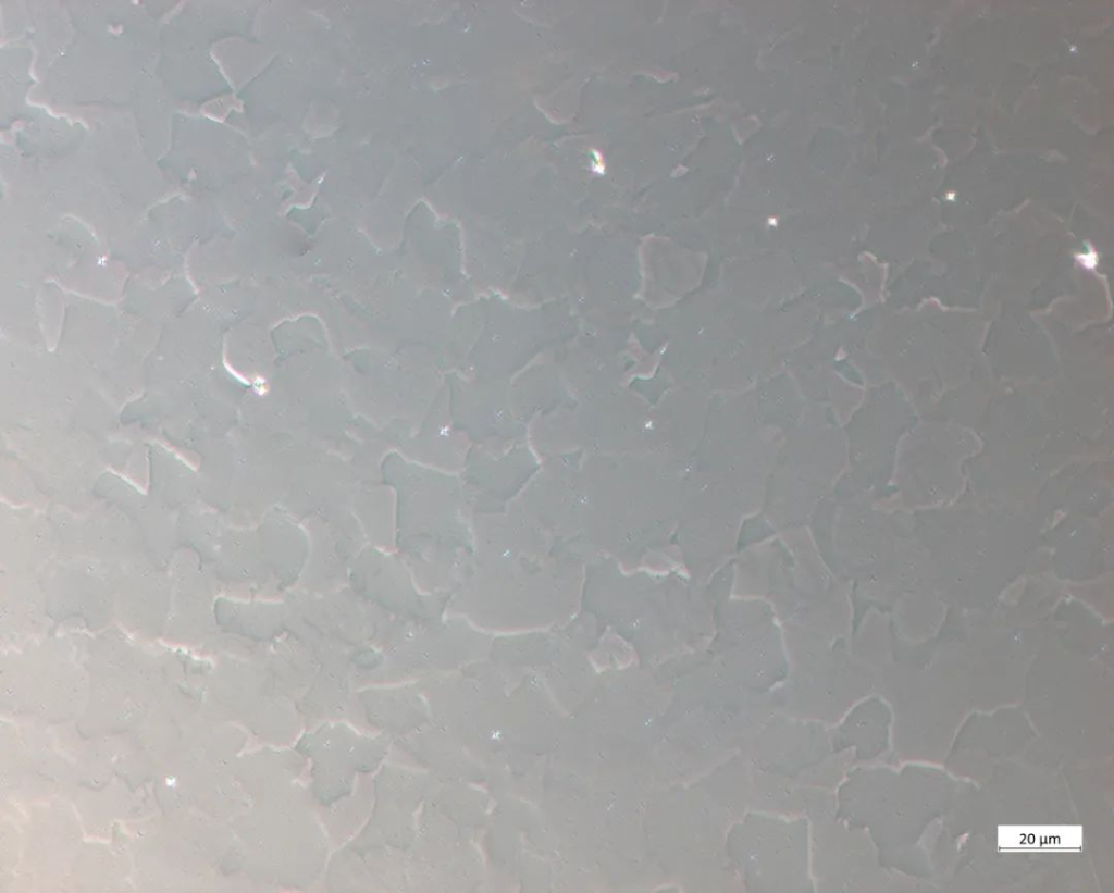
Let’s look at the different morphological characteristics of a set of typical structures in the etched state (polished state in the differential interference field). The photos shown in Figures 9 to 12 are the imaging results of the same picture of the ferrite + pearlite structure in different fields of view. The difference in imaging between different functional fields of view can be seen intuitively.
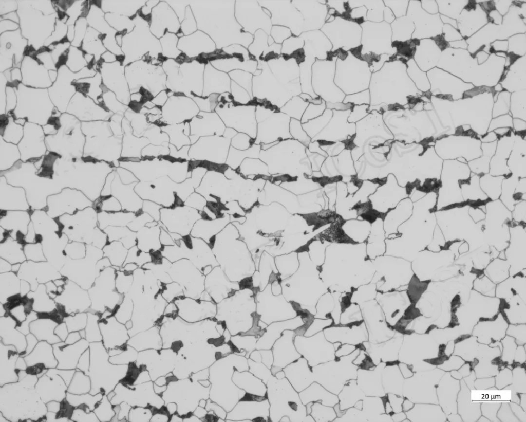
Ferrite + pearlite, clear structure
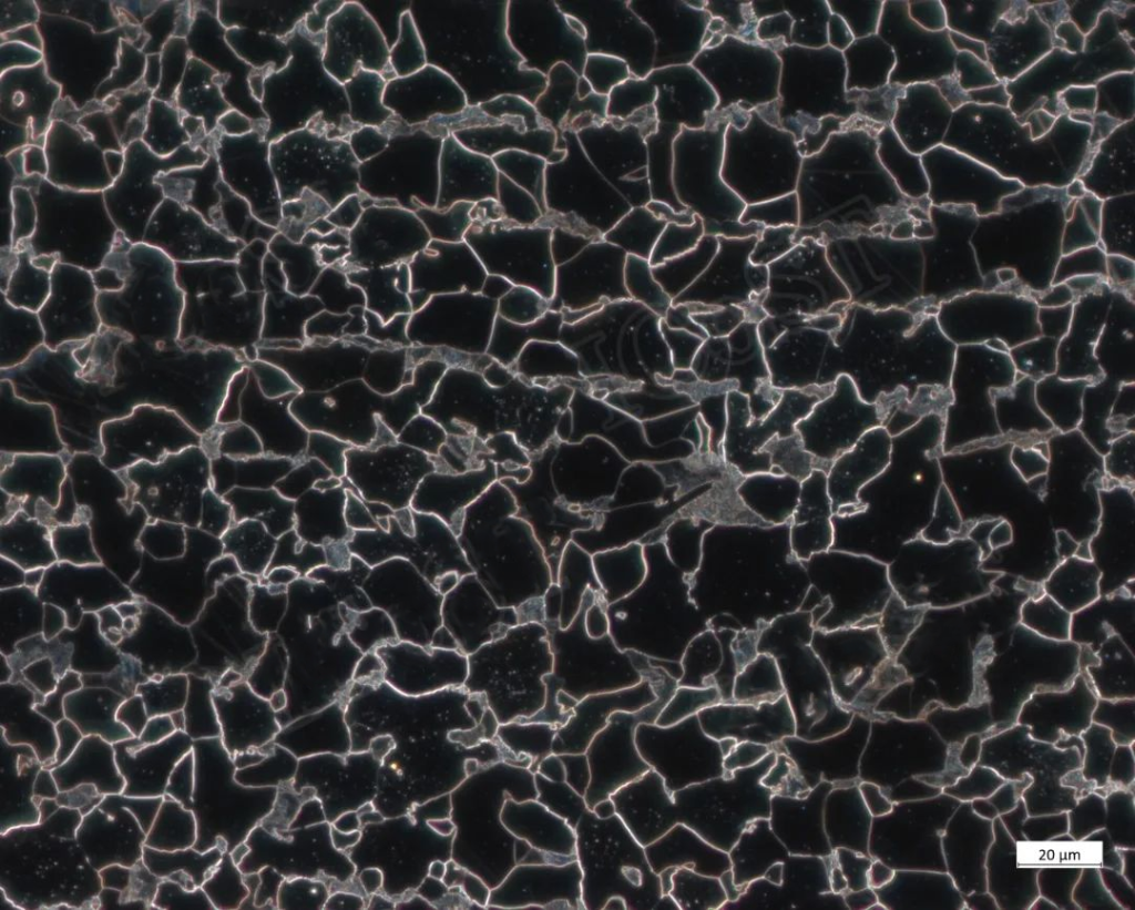
Bright grain boundaries
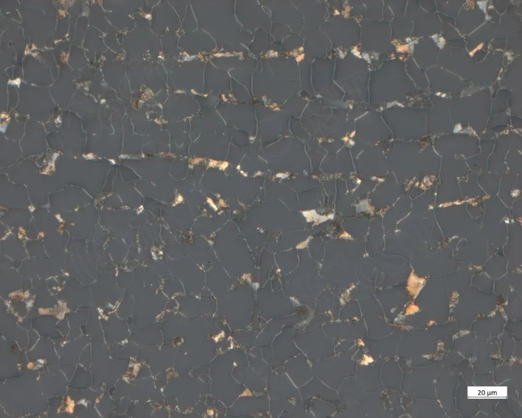
F (dark gray) + P (yellow-white)
The grains have a relief feel (polished state)
Generally speaking, a bright field is suitable for observing etched structures, and most etchable metallographic structures can be imaged by a bright field. The dark field can identify extremely fine grinding marks, and can also identify the color of non-metallic inclusions. For example, copper oxide appears light blue when observed in a bright field under white light illumination, but its true ruby color can be seen when observed in a dark field. Polarized light can also identify non-metallic inclusions; in addition, for some metals and alloys, it is difficult to etch structures or grains, such as some deformed aluminum alloys. When using a polarized field of view, grains with different orientations are visible; at the same time, after undergoing a large number of The preferred orientation of plastically deformed metals can also be determined by polarizing the field of view. Based on the characteristics of visible grains with different orientations, the application of polarization can also be expanded. For example, when analyzing new materials, it can also be easily judged whether there are unetched phases in the polarized field of view. The differential interference field of view adds an obvious relief shape to the polarized field of view, with more obvious contrast, which is conducive to automatic quantitative work and adding more details. Its biggest feature is that it does not require etching; in addition, the addition of λ- The film can be photographed in color metallography to improve the accuracy in quantitative analysis.
In short, the different functions of a metallographic microscope are complementary to each other. Once you understand the principles of the formation of different fields of view, you can choose the appropriate observation mode or function according to the characteristics of the sample itself and the purpose of observation to better complete the metallographic analysis. an important part of the job.