As early as the 1st century BC, people discovered that using spherical transparent objects to observe tiny objects could magnify and image them. Later, there was a gradual understanding of the principles behind how spherical glass surfaces could magnify objects. By 1590, craftsmen in the Netherlands and Italy had created magnifying instruments similar to microscopes. Around 1610, Italian scientist Galileo Galilei and German astronomer Johannes Kepler, while studying telescopes, adjusted the distance between the objective lens and the eyepiece, establishing a reasonable optical path for microscopes. Optical artisans of the time then engaged in manufacturing, promoting, and improving optical microscopes based on these principles.
The concept of using lenses to magnify objects had roots in antiquity. Ancient civilizations like the Egyptians and Greeks experimented with lenses and understood their magnifying properties. However, it was during the Renaissance period that significant advancements in optical technology were made, leading to the development of early microscopes.
The basic principle behind optical microscopes involves the use of lenses to bend light rays, magnifying the image of the object being observed. These microscopes typically consist of an objective lens near the specimen, which gathers light and forms an initial image, and an eyepiece or ocular lens that further magnifies this image for the viewer.
Over time, optical microscopes underwent numerous improvements, such as the incorporation of multiple lenses to reduce aberrations and enhance clarity, the introduction of adjustable focus mechanisms, and the development of specialized illumination techniques to improve visibility and contrast. These advancements revolutionized scientific research by enabling detailed observations of microscopic structures and organisms, contributing significantly to fields like biology, medicine, materials science, and more.
These simple magnifying glasses evolved into advanced optical systems known as optical microscopes, allowing us to see and understand the microscopic world beyond the limits of our perception.
Today, optical microscopy is a core technology in many fields of science and technology, including life sciences, biology, materials science, nanotechnology, industrial inspection, forensics, and more. We will first explore the basic working principles of light microscopy before moving on to discuss some of the more advanced forms of light microscopy commonly used today and compare their advantages and disadvantages for different applications.
§1 What is an optical microscope?
An optical microscope (abbreviated as OM) uses optical principles to magnify and image tiny objects that cannot be distinguished by the naked eye so that people can extract fine structural information.
§2 Parts of a microscope and how an optical microscope works
Basically, a microscope consists of two subsystems: an illumination system that illuminates the sample and an imaging system that produces a magnified image of the light interacting with the sample, which can then be viewed with the eye or using a camera system.
Early microscopes used illumination systems that included sunlight, which was collected through mirrors and reflected onto the specimen. Today, most microscopes use artificial light sources such as light bulbs, light-emitting diodes (LEDs), or lasers to create more reliable and controllable illumination systems that can be customized for a given application. In these systems, light from a source is typically collected using a condenser lens, which is then shaped and optically filtered before being focused onto the sample. Shaping light is critical to achieving high resolution and contrast, and often involves controlling the area of the sample that is illuminated and the angle at which light strikes it. Optical filtering of the illumination light, using optical filters that modify its spectrum and polarization, can be used to highlight certain features of the sample.
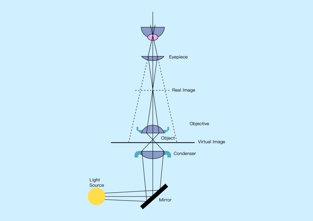
The imaging system collects the illumination light that interacts with the sample and produces a magnified image that can be viewed (see Figure 1 above). This is achieved using two main sets of optical elements: first, the objective collects as much light as possible from the sample, and second, the eyepiece delivers the collected light to the observer’s eye or camera system. Imaging systems may also include elements such as apertures and filters that select certain portions of the light from the sample, such as seeing only light that has been scattered from the sample, or seeing only light of a specific color or wavelength. As is the case with illumination systems, this type of filtering is useful for singling out certain features of interest that remain hidden when all light from the sample is imaged.
Overall, illumination and imaging systems play a key role in the performance of optical microscopes. In order to get the most out of light microscopy in your application, it’s important to have a good understanding of how basic light microscopy works and the variations that exist today.
Simple compound microscope
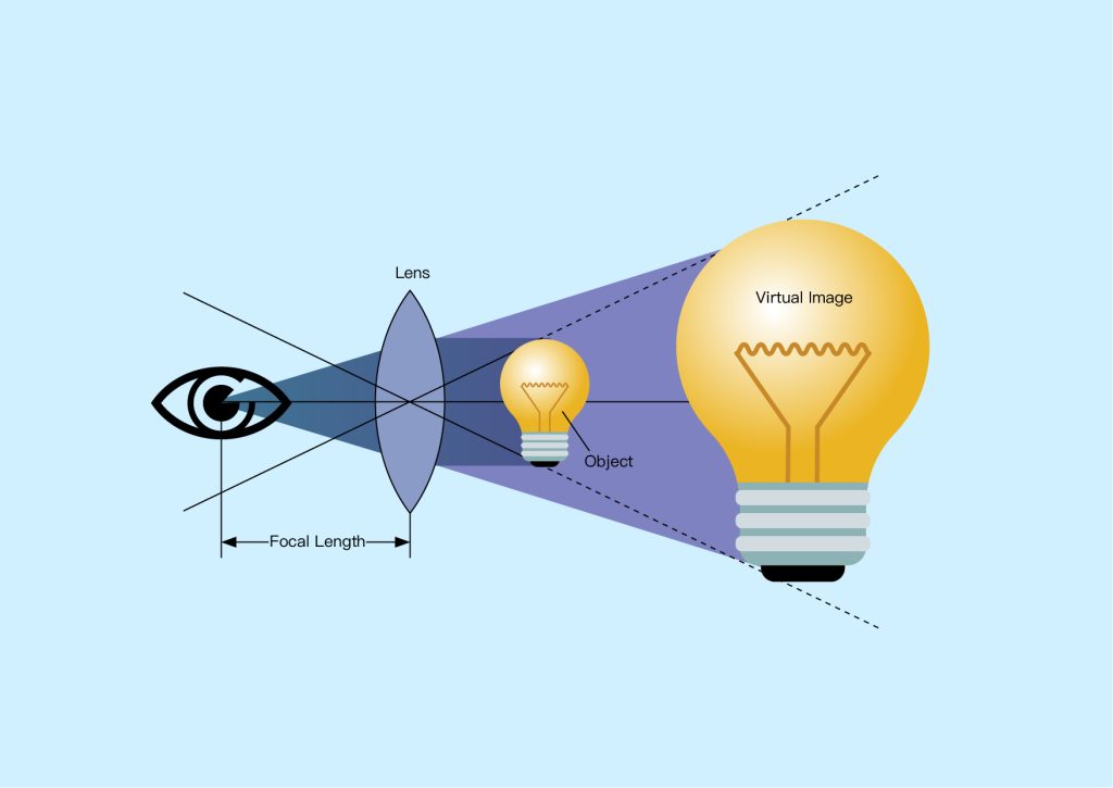
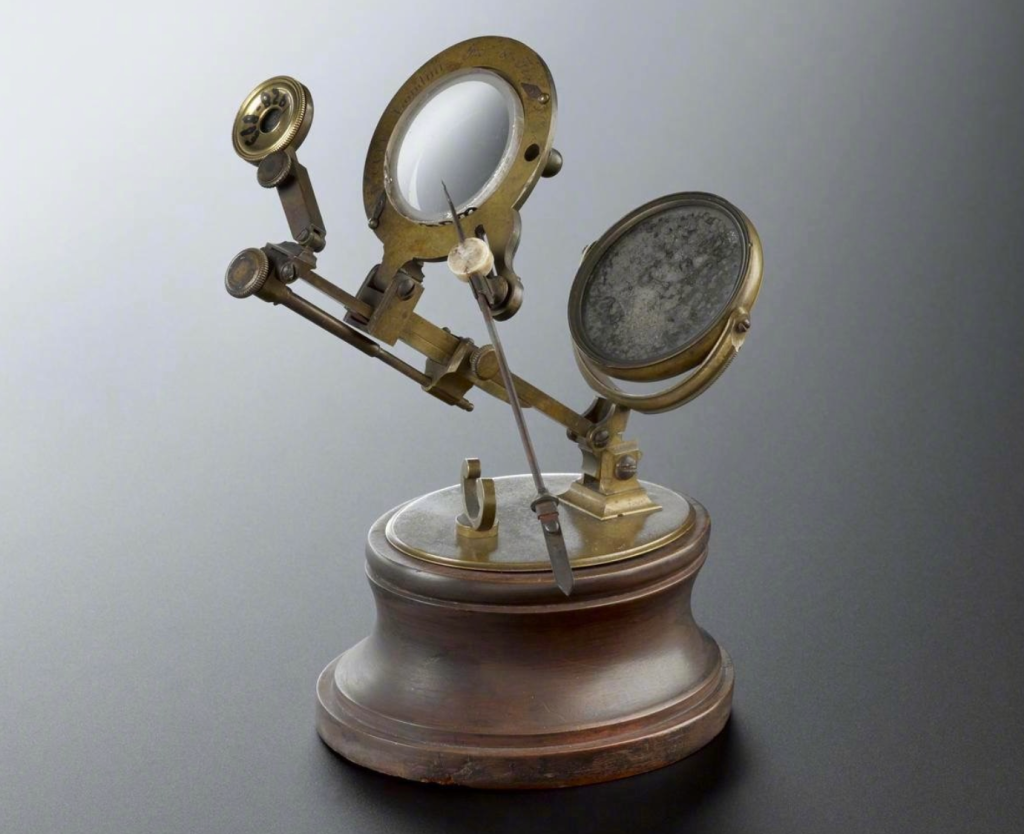
A single lens can be used as a magnifying glass, increasing the apparent size of an object when it is brought closer to the lens. When we look at an object through a magnifying glass, we see an enlarged and virtual image of the object. This effect is used in simple microscopes, which consist of a single lens that images a sample clamped in a frame and illuminated from below, as shown in Figure 2 below. This type of microscope can typically achieve magnifications of 2-6x, which is sufficient for studying relatively large samples. However, achieving higher magnification and better image quality required the use of more optical components, which led to the development of compound microscopes (Figure 3 below).
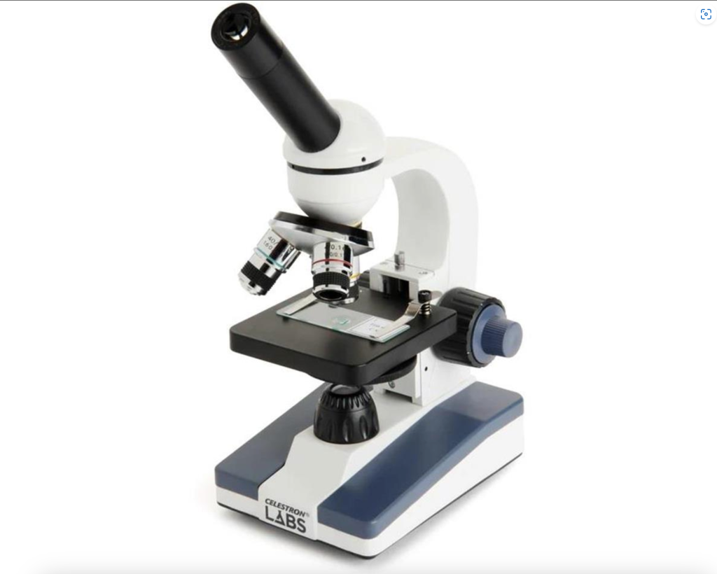
In a compound microscope, the sample is illuminated from the bottom to observe transmitted light, or from the top to observe reflected light. Light from the sample is collected by an optical system consisting of two main lens groups: the objective and the eyepiece, each of which is power multiplied to achieve higher magnification than a simple microscope. Objective lenses collect light from the sample and typically provide a magnification of 40-100x. Some compound microscopes feature multiple objectives on a rotating turret called a nose piece, allowing the user to choose between different magnifications. The image from the objective lens is picked up by the eyepiece, which again magnifies the image and delivers it to the user’s eye, with a typical eyepiece magnification of 10x.
The smallest feature size that can be observed with a standard optical microscope is determined by the optical wavelength used (λ) and the resolution of the microscope objective and is defined by its numerical aperture (NA), with a maximum value of NA =1 for an aerial objective. The Rayleigh criterion gives the resolution limit defining the smallest distinguishable feature size (r):
r=0.61×(λ/NA)
For example, using green light with a wavelength of 550nm and an objective with a typical NA of 0.7, a standard optical microscope can resolve features as low as 0.61×(550nm)/0.7≈480nm, which is sufficient to observe cells (typically 10µm in size), but not sufficient Observe the details of smaller organisms, such as viruses (typically 250-400nm). To image smaller features, more advanced and expensive objectives with higher NA and shorter wavelengths can be used, but this may not be suitable for all applications.
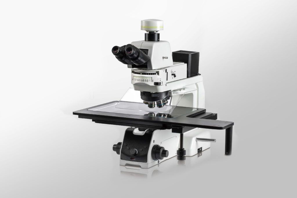
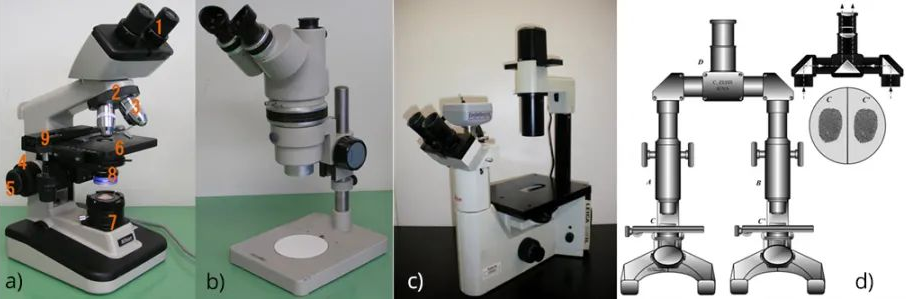
In a standard compound microscope (see Figure 4a below), the sample (usually on a glass slide) is mounted on a stage that can be moved manually or electronically for greater precision, the illumination system is located in the lower part of the microscope, and the imaging system is high in the sample. However, microscope bodies can often be adapted to specific uses. For example, a stereomicroscope (see Figure 4b below) features two eyepieces at a slight angle to each other, allowing the user to see a slightly three-dimensional image. In many biological applications, an inverted microscope design (see Figure 4c below) is used in which the illumination system and imaging optics are below the sample stage to facilitate placement of cell culture vessels, etc., on the sample stage. Finally, comparison microscopes (see Figure 4d below) are commonly used in forensic medicine.
§3 12 different types of optical microscopes
Below, we introduce 12 different types of light microscopy techniques, discussing their main principles of operation and the advantages and disadvantages of each technique.
● Bright field microscope
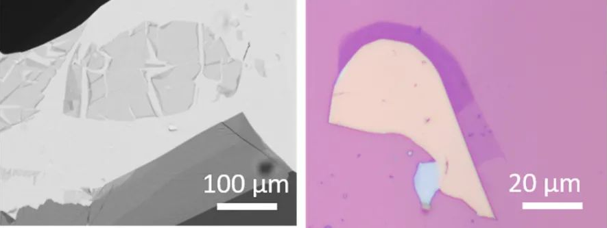
Brightfield microscopy (BFM) is the simplest form of optical microscopy, illuminating the sample from above or below and collecting the transmitted or reflected light to form an image that can be viewed. Contrast and color in images result from absorption and reflection varying within the sample area. The BFM was the first optical microscope to be developed, using a relatively simple optical setup that allowed early scientists to study microorganisms and cells in transit. Today it is still very useful for the same purposes and is also widely used to study other partially transparent samples, such as thin materials in transmission mode (Figure 5 below), or microelectronics and other small structures in reflection mode.
● Darkfield microscopy
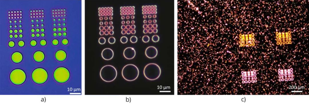
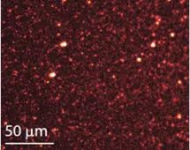
Darkfield microscopy is a technique that collects only the light scattered by the sample. This is achieved by adding holes that block direct imaging of the illumination light so that only illumination light scattered by the sample is seen. In this way, darkfield microscopy highlights small structures that scatter light (Figure 6 below) and is very useful for revealing features that are not visible in BFM without modifying the sample in any way. However, since the only light seen in the final image is scattered light, darkfield images can be very dark and require high illumination power, which can damage the sample.
● Phase contrast microscope
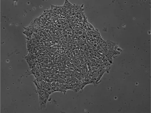
Phase contrast microscopy (Brightfield microscopy, PCM) is a technique for visualizing optical phase changes caused by changes in the optical path length of the sample. This can image transparent samples that produce little or no contrast in BFM, such as cells (as shown below) 7). Since optical phase shifts are not easily visible to the naked eye, phase contrast microscopy requires additional optical components to convert the sample-induced phase shifts into visible brightness changes in the final image. This requires the use of apertures and filters to manipulate the illumination and imaging systems. These shape and selectively phase-shift light from the sample (carrying the phase information of interest) and illumination light so that they constructively interfere with the eye or detector to create a visible image.
● Differential interference microscopy
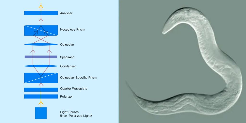
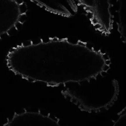
Similar to PCM, differential interference contrast microscopy (DICM) visualizes transparent samples (such as living unstained cells) by converting the optical phase caused by changes in the optical path length of the sample into visible contrast.
However, compared to PCM, DICM enables higher resolution images with reduced sharpness and image artifacts introduced by the optics required for PCM. In DICM, the illumination beam is polarized by a linear polarizer, whose polarization is rotated so that it splits into two polarized beams with perpendicular polarization and a small (usually less than 1µm) separation. After passing through the sample, the two beams recombine and interfere with each other. This creates an image with a contrast proportional to the difference in phase of light between the two polarized beams, hence the name “difference” interference microscopy.
The image produced by DICM appears as a three-dimensional image related to the direction of displacement between the sampling beams, which results in bright or dark areas at the edge of the sample, depending on the sign of the optical phase difference between the two (Figure 8 below).
● Polarizing microscope
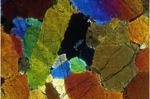
In polarized light microscopy, the sample is illuminated with polarized light, and the detection of the light is also sensitive to polarization. To achieve this, a polarizer is used to control the illumination light polarization and limit the polarization detected by the imaging system to only one specific polarization. Typically, the illumination and detection polarizations are set perpendicular so that unwanted background illumination light that does not interact with the sample is strongly suppressed. This configuration requires a birefringent sample, which introduces a rotation of the polarization angle of the illuminating light so that it can be detected by the imaging system, for example, observing the birefringence of the crystals and changes in their thickness and refractive index (Figure 9 below).
● Fluorescence microscope
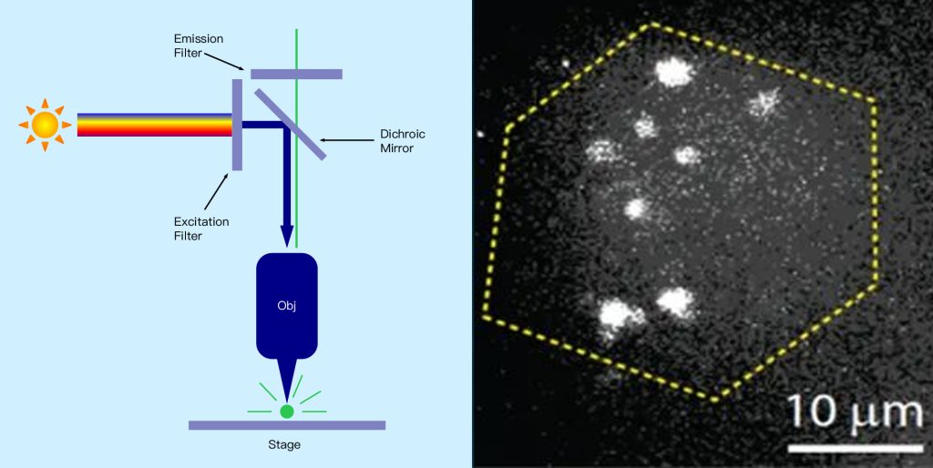
Fluorescence microscopy is used to image samples that fluoresce, that is, they emit light of longer wavelengths when illuminated with shorter wavelengths of light. Examples include biological samples that are inherently fluorescent or have been labeled with fluorescent markers, as well as single molecules and other nanoscale fluorophores. This technique uses a combination of filters that block short-wavelength illumination light but allow longer-wavelength sample fluorescence to pass, so the final image only shows the fluorescent part of the sample (Figure 10 below). This allows picking out and visualizing the distribution of fluorescent particles or cells of interest that have been stained by the dye from a sample consisting of many other non-fluorescent particles.
At the same time, fluorescence microscopy can also overcome the resolution limitations of traditional optical microscopy by labeling particles smaller than this limit. For example, viruses can be tagged with fluorescent markers to reveal their location. In the case of biological samples, fluorescent proteins, such as green fluorescent protein, can be expressed. Combined with various novel forms of sample illumination, this advantage of fluorescence microscopy enables “super-resolution” microscopy technology, breaking the resolution limitations of traditional optical microscopy. One of the major limitations of fluorescence microscopy is photobleaching, in which markers or particles stop emitting fluorescence because the process of absorbing illuminating light eventually changes its structure so that it no longer emits light.
● Immunofluorescence microscopy
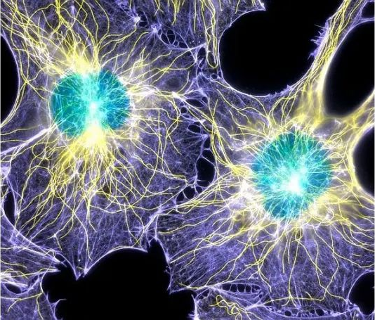
Immunofluorescence microscopy is a specific change in fluorescence microscopy that is primarily used to visualize biomolecules within the cells of microorganisms. Here, antibodies labeled with fluorescent markers or inherently fluorescent bind to biomolecules of interest, revealing their location. (As shown in Figure 11 below)
● Confocal microscopy
Confocal microscopy is a microscopy technique that can image scatter or fluorescence from a sample point by point. Rather than illuminating and imaging the entire sample at once, a spot of illumination originating from a point source is scanned over the sample area, and a sensitive detector detects only the light from that spot, producing a 2D image. This method allows imaging of weak signal samples at high resolution because unwanted background signals from outside the sampling point are effectively suppressed. Here, the wavelength and objective used limit the size of the imaging spot in all three dimensions. This allows 2D images to be made at different depths within the sample by moving the objective lens to different distances from the sample. These 2D image “slices” can then be combined to create a 3D image of the sample, which is not possible with the other widefield microscopy techniques discussed and also allows sample dimensions to be measured in 3D. The trade-off for these advantages is that the image cannot be captured in one go, but rather must be constructed point by point, which can be very time-consuming and hinder real-time imaging of the sample (see Figure 12 below).
● Two-photon microscope
Two-photon microscopy (TPM) is a variation of fluorescence microscopy that uses two-photon absorption to excite fluorescence instead of single-photon excitation. Here, fluorescence is excited by absorbing a combination of two photons with approximately half the energy required for excitation by a single photon. For example, in this scheme, a fluorophore that is normally excited by a single blue photon can be excited by two near-infrared photons. In TPM, the image is built point by point, just like in confocal microscopy, that is, two-photon excitation points are scanned over the sample and the sample fluorescence is detected by a sensitive detector. The large difference in excitation and fluorescence energy results in multiple advantages compared to conventional fluorescence microscopy: firstly, it allows the use of longer excitation wavelengths, with less scattering within the sample and therefore deeper penetration, allowing for detection of the sample below its surface. Perform imaging and create 3D sample images. At the same time, because the excitation energy is much lower, photobleaching is greatly reduced, which is useful for fragile samples. The fluorescence background around the excitation point is also greatly reduced because effective two-photon absorption only occurs at the focus of the excitation beam, so fluorescence from a small portion of the sample can be observed (Figure 13 below).
One disadvantage of TPM is that the probability of two-photon absorption is much lower than that of single-photon absorption, so high-intensity illumination, such as a pulsed laser, is required to achieve practical fluorescence signal intensity.
● Light sheet microscopy
Light-sheet microscopy is a form of fluorescence microscopy in which a sample is illuminated by a thin “sheet” of light perpendicular to the direction of observation, allowing only thin sections of the sample (usually a few microns) to be imaged. A 3D image is formed by taking a series of images while the sample is rotating in a light sheet. This requires that the sample be mostly transparent, which is why this technique is often used to form 3D images of small transparent biological structures, such as cells, embryos and organisms. (As shown in Figure 14 below)

● Total internal reflection fluorescence microscopy
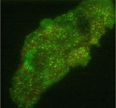
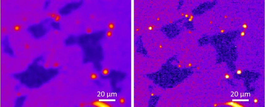
Total internal reflection fluorescence (TIRF) is a fluorescence microscopy technology that can produce 2D fluorescence images through extremely thin (about 100nm thick) sample sections. This is achieved by excitation of the sample’s fluorescence by the evanescent field of illuminating light, which occurs when it undergoes total internal reflection at the boundary between two materials with different refractive indices (n). The evanescent field has the same wavelength as the illuminating light but is tightly bound to the interface. In TIRF microscopy, the excitation light typically undergoes total internal reflection at the interface between the glass slide (n = 1.52) and the aqueous medium in which the sample is dispersed (n = 1.35). The intensity of the evanescent field decreases exponentially with distance from the interface, such that only fluorophores close to the interface are observed in the final image. This also results in a strong suppression of fluorescence background from areas outside the section, which allows the pickup of weak fluorescence signals, for example when localizing single molecules. This makes TIRF ideal for observing weak signals from fluorescent proteins involved in cell-cell interactions (Figure 15 below), but also requires the sample to be dispersed in an aqueous medium, which may limit the types of samples that can be measured.
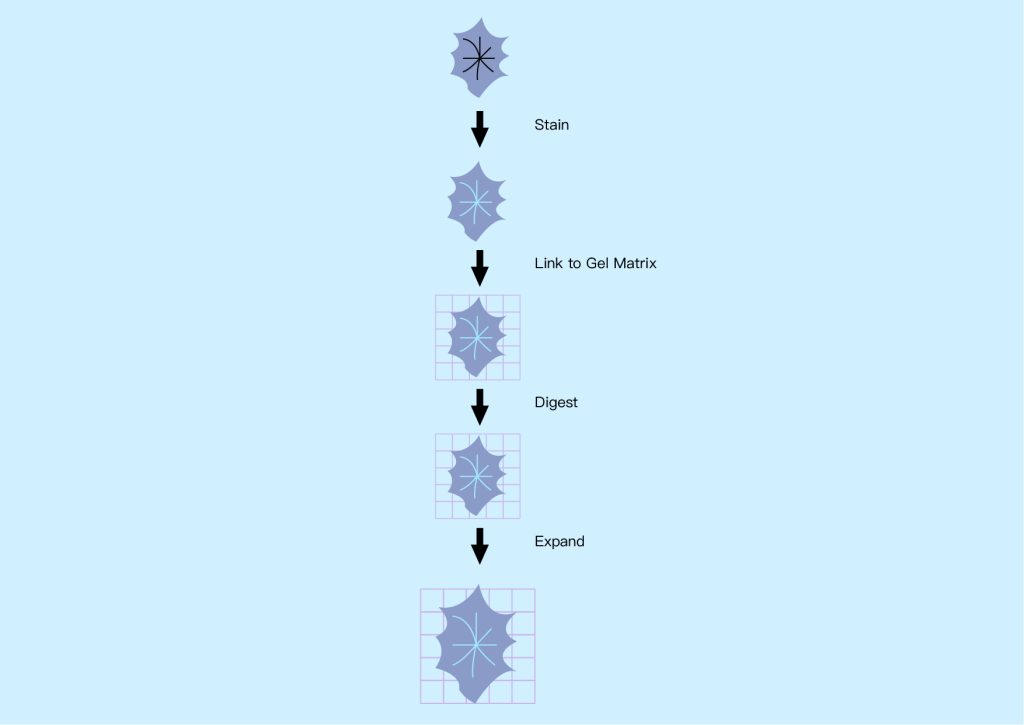
● Expansion microscope
The basic concept behind expansion microscopy is to increase the size of samples that typically require high-resolution microscopy so that they can be imaged using standard microscopy techniques, especially fluorescence microscopy. This applies to preserved specimens such as biomolecules, cells, bacteria and tissue sections, which can be expanded uniformly in all dimensions (isotropically) up to 50 times using the chemical process shown in Figure 16 below. Expanding the sample can isolate individual features of interest that are normally hidden, making them transparent so their interiors can be imaged.
§4 Convolution in optical microscopy
In addition to adapting optical systems to specific use cases, modern optical microscopy also takes advantage of digital image processing, such as image deconvolution. This technology can improve the spatial resolution and positioning accuracy of images captured by optical microscopes by compensating for the inherent blur of the optical system itself. This blur can be measured during the calibration step and can then be used to deconvolve the image, thereby reducing the blur. By combining high-performance optics with advanced image processing, digital microscopes can push the limits of resolution to peer deeper into the microscopic world. (As shown in Figure 17 below)
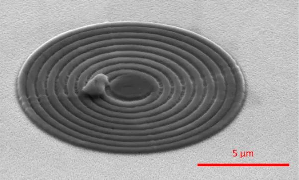
§5 Optical and electron microscopy
Optical microscopy typically uses light wavelengths in the visible spectrum, whose spatial resolution is inherently limited due to the Rayleigh criterion to approximately half the wavelength used (up to approximately 200 nm). However, even using objectives with high NA and advanced image processing cannot overcome this fundamental limitation. In contrast, observing smaller structures requires the use of shorter wavelengths of electromagnetic radiation. This is the basic principle of electron microscopy, where electrons are used instead of visible light to illuminate the sample. Electrons have a much shorter relevant wavelength than visible light, so magnifications of up to 10,000,000 times can be achieved and even individual atoms can be resolved. (As shown in Figure 18 below)
§6 Summary and conclusion
Optical microscopy is a powerful tool that can be used to examine small samples in a variety of applications. By adapting the illumination and imaging techniques for specific use cases, high-resolution images can be obtained that provide insight into the microstructure and processes within the sample. In this article, we discuss the characteristics, advantages, and disadvantages of various light microscopy techniques, which differ in the way light is illuminated and collected.
Microscopy technology comparison table
| Types of microscopes | Advantages | Technical limitations | Typical applications |
| Darkfield microscopy | has a relatively simple structure and few optical components | Low-contrast, completely transparent objects cannot be imaged directly and may need to be dyed | Imaging colored or dyed samples and partially transparent materials |
| Dark field microscopy | Displays small structures and surface roughness, allowing imaging of unstained samples | The high illumination power required damages the sample and only scattered image features are visible | Intracellular particle imaging, surface detection |
| Phase Contrast Microscopy | Enables imaging of transparent samples | Bright-field microscope | Track cell movement, image larvae |
| Differential Interference Contrast Microscopy | Higher resolution than PCM | Complex optical setup, high illumination power required can damage sample, often darker images | High-resolution imaging of live, unstained cells and nanoparticles |
| Polarizing Microscopy | Strong background suppression from non-birefringent areas of the sample, allowing measurement of sample thickness and birefringence | Requires birefringent samples | Imaging collagen, revealing grain boundaries in crystals |
| Fluorescence microscopy | Allows picking out individual fluorophores and specific regions of interest in a sample, resolution limitations can be overcome | Requires fluorescent sample and sensitive detector, photobleaching reduces signal | Imaging cellular components, single molecules, proteins |
| Immunofluorescence microscopy | Visualizing specific biomolecules using antibody targeting | Extensive sample preparation, requiring fluorescent samples, photobleaching | Identifying and tracking cells and proteins |
| Confocal microscopy | Low background signal, can create 3D images | Complex optical setup, and high illumination power required can damage sample, often dark images | 3D cell imaging, imaging samples with weak fluorescence signals, surface analysis |
| Two-photon microscopy | Deep sample penetration, low background signal, less photobleaching | Slow imaging speed, requiring complex optical systems and high-power illumination | Neuroscience, deep tissue imaging |
| Light sheet microscopy | Images only very thin sections of the sample, 3D images can be created by rotating the sample | Imaging is slow and requires complex optical systems | 3D imaging of cells and organisms |
| Total internal reflection fluorescence microscopy | Powerful background suppression, extremely fine vertical sectioning | Imaging is limited to thin areas of the sample, requires complex optical systems, and the sample needs to be in aqueous media | Single molecule imaging, imaging molecular transport |
| Expansion Microscopy | Increases the effective resolution of standard fluorescence microscopy | Requires chemical treatment of sample, not suitable for living samples | High-resolution imaging of biological samples |