1. Microscope components
A compound microscope is an optical instrument composed of a combination of multiple lenses. Its working principle is similar to a simple magnifying glass, that is, it uses a single lens to magnify small objects into images so that people can observe the fine structures of small objects through the naked eye. A simple magnifying glass works by placing an object within the focal length of a single lens to obtain a magnified virtual image of the object. Relay lens systems replace single lenses in microscopes, allowing the objective and eyepieces to work together and reflect the image of the object to the eye or sensor, depending on the application.
There are two components in a microscope that are responsible for increasing the magnification of the overall system: the objective lens and the eyepieces.
Objective lens
The objective lens is the optical element closest to the object. Its function is to obtain a magnified real image of the object and reflect it to the eyepiece. The objective lens is the most important part of the microscope and is used to produce baseline magnification.
Eyepiece
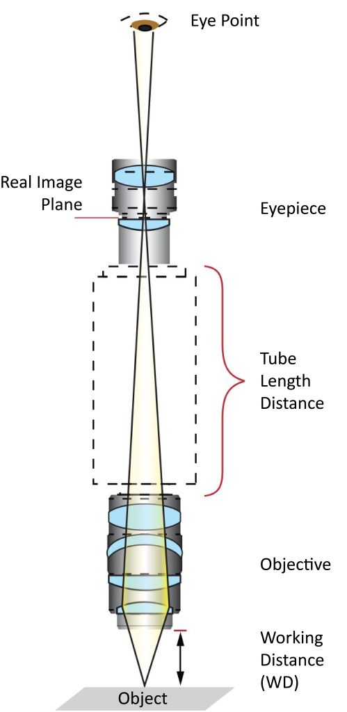
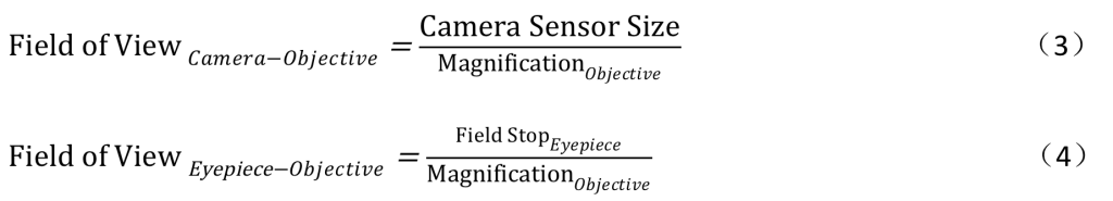
The eyepiece is the optical element closest to the human eye or sensor. Its function is to further magnify the real image formed by the objective lens to form a virtual image. Eyepiece magnification is usually 10x, but sometimes it ranges from 1 to 30x. Figure 1 shows the components of a compound microscope. Additionally, Equation 1 illustrates how the overall system magnification of a microscope is calculated.
MagnificationSystem = MagnificationObjective×MagnificationEyepiece (1)
2. Eyepiece
Eyepieces played an important role in the early days of the microscope because they were the only optical element that allowed people to see the details of tiny objects with the naked eye. Today, people use analog or digital cameras to reflect an image of an object onto a monitor or screen. Microscope eyepieces are usually composed of a field lens and an eyepiece lens, and come in a variety of designs, each of which provides a field of view that is larger than that produced by a single lens.
3. Lighting
Like choosing the right eyepiece or objective, lighting is an important part of a microscope. Choosing the right lighting plays a key role in reaching decisive conclusions in your experiments. Before deciding which type of lighting setup to use, the first things to consider are the application setup, the objects you want to observe, and the expected results.
Koehler lighting
Many microscopes choose to use backlight illumination rather than traditional direct illumination, which often results in over-saturated images of objects. A specific type of backlight illumination used in microscopy applications is Koehler illumination. In Koehler lighting, incident light from a lighting source (such as a light bulb) emits sufficient light to illuminate an object from behind (Figure 2). It is equipped with two kinds of convex lenses, namely: condenser lens and collecting lens. It is mainly designed to provide sufficient brightness and uniform illumination on the object plane and imaging plane, so that the real image of the object obtained by the objective lens can be reflected through the eyepiece. This is very important as it ensures that the user does not magnify the filament of the bulb into an image. Because backlight lighting illuminates objects from behind, this phenomenon is also called bright field lighting.
Brightfield illumination
To observe an object using brightfield illumination, the object’s opacity must be changed. If the object’s opacity does not change, the lighting source will produce blurry black spots around the object. The resulting image is the relative contrast between part of the object and the light source. In most cases, unless the object is extremely transparent, with sufficient clarity or resolution, one will be able to see every part of the object through the resulting image. When the transparency of an object prevents the microscope from using brightfield illumination to observe the details of the object, darkfield illumination can be used.
Darkfield illumination
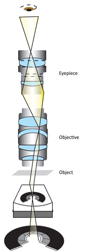
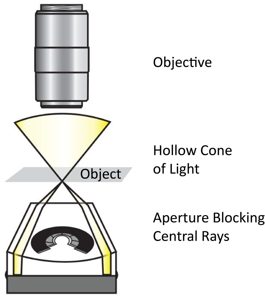
In a microscope using darkfield illumination, light does not enter the objective lens directly but instead strikes the object obliquely. But the important thing to remember is that the light is still illuminating the object on the object plane. Images obtained under darkfield illumination create a strong contrast between light and dark between a transparent object and the light source. Darkfield illumination in a microscope setup creates a light source that creates an inverted beam of light that blocks the central beam of the light source, causing the light to change its path and strike the object obliquely. Figure 3 shows the darkfield illumination setup. The hollow cone of light is the numerical aperture of the objective. In contrast, no light is blocked in a brightfield lighting setup. Darkfield illumination is designed to allow light to illuminate objects but not enter the optical system, so it is suitable for observing transparent objects.
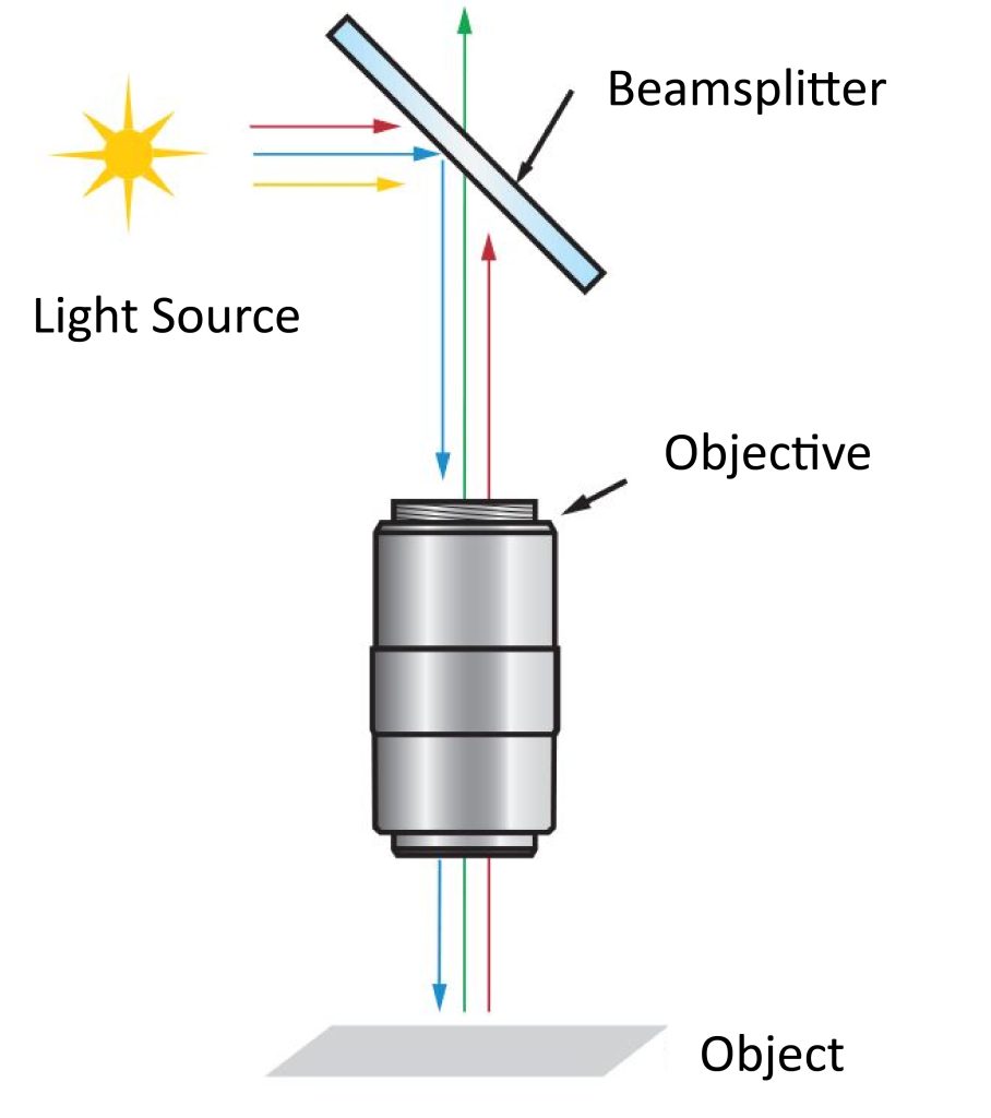
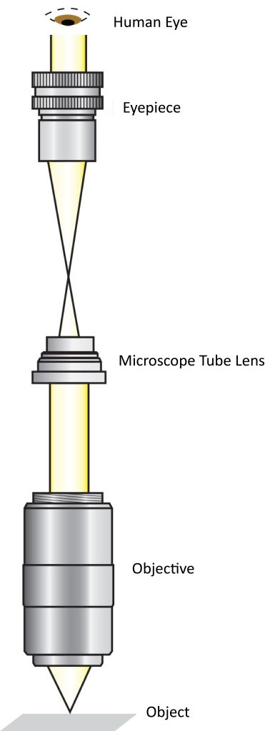
The third type of illumination used in microscopes is epi-illumination. The beam of epi-illumination is generated above the objective lens. Therefore, objective lenses and epi-illumination sources can be used in place of the Koehler illumination setup. The biggest advantage of epi-illumination design is that it uses the objective lens to complete most of the lighting, so it has a compact lighting design. Figure 4 illustrates an epi-illumination setup commonly used in fluorescence applications.
4. Objective lens
The objective lens is the most complex optical element of a microscope. It is a lens group composed of several lenses. Its main function is to make the object form a magnified real image. Objective lenses typically have magnifications between 2 and 200x. Objective lenses can be divided into two main categories: traditional refractive objectives and reflective objectives. Each broad category is further divided into the following two types: finite conjugate and infinite conjugate (far-field correction). To choose the most appropriate objective lens, it is necessary to understand each of the major categories of objective lenses and the advantages of their individual types.
There are two main types of objectives: traditional refractive objectives and reflective objectives
Objective lens: refractive type
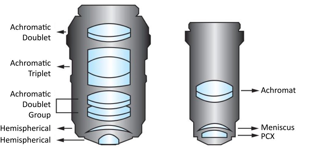
Refractive objectives are the most common category of objectives used in microscopes. The refractive design of the objective lens allows the optical elements to refract or bend the light as it passes through the microscope. The surface of each optical element is coated with an AR coating, which reduces back reflections and improves overall light flux. Refractive objectives are commonly used in machine vision applications that require extremely high resolution. There are many types of refractive objectives, each using a different optical configuration. Refractive objective designs can range from achromatic objectives with two elements (an achromatic lens and a meniscus lens) to plan apochromatic objectives with fifteen elements (Figure 5). Plan apochromatic objectives are the most complex high-end objectives in design. The objective itself can complete chromatic aberration correction and flat field correction.
Objective lens: Reflective type
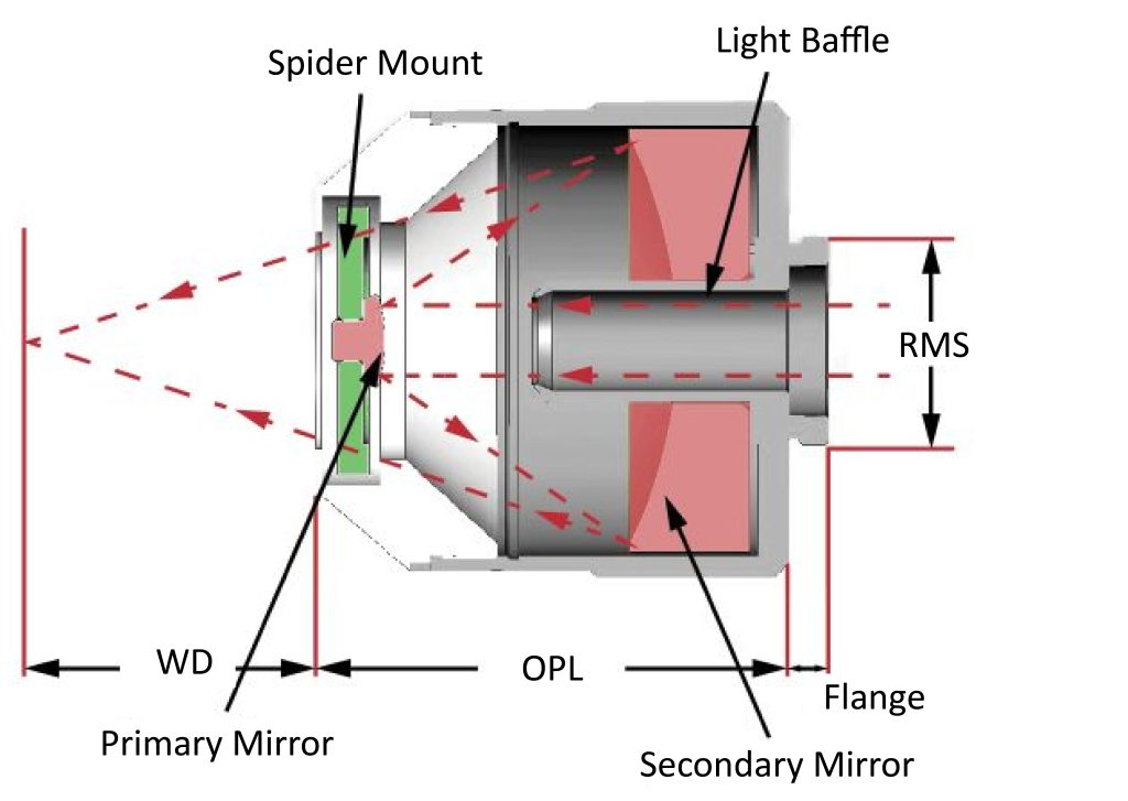
A reflective objective is an objective that has a reflective or mirror design. Even though reflective objectives have most of the same degree of correction as refractive objectives, it is still often overlooked when choosing an objective. The reflective objective lens is composed of a first and a second mirror system (Figure 6). Its function is to magnify the image of the observed object and then reflect the image into the eyepiece. Edmund Optics® offers a variety of different designs of reflective objectives, with the most popular design being the Schwarzschild reflective objective. Because light is reflected by the metal surface rather than refracted by the glass surface, reflective objectives do not have the aberration problems faced by refractive objectives, so there is no need for additional design to correct aberrations. In addition, since the main surface material of the reflective objective lens is a mirror film rather than a glass substrate, it can provide higher light efficiency and higher resolution for imaging details. Another advantage of reflective objectives is their longer working distance. Compared with traditional refractive objectives, the mirrors they use can work in the spectral range of the ultraviolet and infrared regions.
Main concepts and specifications
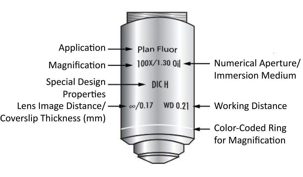
The specifications for most microscope objectives are listed on the objective body and include: objective design/standards, magnification, numerical aperture, working distance, lens-to-image separation, and coverslip thickness correction. Figure 7 shows a description of the microscope’s objective lens specifications. Since all specifications are listed on the main body of the objective lens, users can easily understand the relevant functions of the objective lens used when installing several objectives for an application. For other specifications such as focal length, field of view, wavelength design, etc., users can easily calculate them or obtain relevant specifications from the supplier or manufacturer.
| Magnification | 1X | 2X | 3X | 4X | 10X | 20X | 40X | 60X | 100X |
| Color Code | Black | Gray | Red | Yellow | Green | Light Blue | Light Blue | Dark Blue | White |
Objective Lens Standard
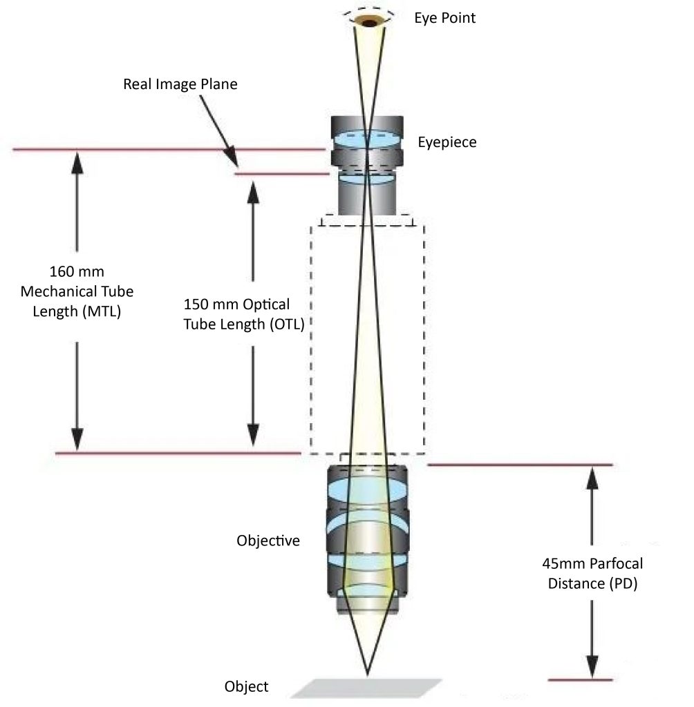
If the standard used for the objective lens is a simple microscope standard (such as DIN or JIS standard), then the main body will list the objective lens specifications required by the system. Most compound microscope design standards adopt German Industrial Standards (Deutsche Industrie Norm, referred to as DIN). The distance between the DIN standard microscope objective flange and the eyepiece flange is 160mm (Figure 8). In addition to DIN standards, we also have microscopes that adopt the Japanese Industrial Standard (JIS). The distance between the JIS standard microscope objective flange and the eyepiece flange is 170mm (Figure 9).
When selecting the appropriate objective lens and eyepiece, the user must take the flange distance of the two lenses into consideration to ensure that after the objective lens magnifies the object into an image, it correctly reflects the image into the eyepiece.
Although DIN standard and JIS standard microscopes have different imaging distances, this distance difference does not have any impact on the optical performance of the microscope, and both can provide the same high-quality imaging. Additionally, microscopes meeting both standards use the same 0.7965″ x 36TPI RMS mounting threads.
DIN and JIS standards have long been factors in the choice of classic compound microscopes. Some microscope manufacturers prefer to list tube lens lengths based on optical properties rather than mechanical properties. Since the eyepiece images the object at the intermediate imaging plane, this will change the tube lens length of the DIN standard microscope to 150mm (Figure 8). Finally, users can also learn about tube lens length by looking at a dimension specifically listed for the objective: the parfocal distance (PD). The parfocal distance is the distance between the objective flange and the object being observed. The standard parfocal distance of DIN objectives is 45mm, while the standard parfocal distance of JIS objectives is 36mm (Figures 8 and 9).

Magnification
Both eyepieces and objective lenses have magnification capabilities and play a very important role in the magnification of the overall microscope system. Magnification is usually expressed as a numerical value and an “X”. Most objectives have a color-coded ring around the body that indicates the objective’s magnification (Figure 7). For example, yellow indicates a magnification of 10x.
Numerical aperture
The numerical aperture (NA) of an objective lens is a function of the focal length and entrance pupil diameter. Objective lenses with large numerical apertures sometimes require the use of immersion oil between the object being observed and the front end of the objective lens. This is because the highest numerical aperture achievable in air is 1 (corresponding to a ray angle of 90°). To obtain larger angles and increase the amount of light entering the objective (Equation 2), an oil immersion objective (typically with a refractive index of 1.5) is used to change the refractive index between the object being observed and the objective. The combination of high numerical aperture objectives and immersion oil provides a simple solution that eliminates the need to spend more money on alternative objectives.
NA=n⋅sinθ (2)
Field of view
The field of view represents the range of objects that the microscope system can observe. The size of the field of view is determined by the magnification of the objective lens. In a microscope system equipped with an eyepiece and an objective lens, the field of view of the objective lens is magnified by the eyepiece, allowing the user to observe objects through the eyepiece. However, in a camera objective system, the field of view is transferred to the camera sensor. The camera sensor is rectangular, so it only receives part of the objective’s full field of view. In contrast, the human retina can see an overall image of the entire field of view. This is why the field of view of a camera microscope system is usually smaller than that of an eyepiece microscope system. Equations 3 and 4 can be used to calculate the field of view for the above system.
Cover glass thickness
When using a microscope to observe specimens containing liquids (such as bacteria, cell cultures, blood, etc.), these tissues or sections should be placed on a coverslip to avoid contamination of the object being observed and the microscope components. Cover glass, also known as microscope cover glass, changes the refraction of light from the object to the objective lens. Therefore, to obtain high-quality imaging, correct optical correction of the objective lens is necessary. This is why a range of coverslip thicknesses are available for optimizing objectives. The cover glass thickness is usually marked after the infinity symbol (that is, the objective is a finite conjugate objective or a far-field corrected objective), and the thickness range is between 0 (no cover glass correction) and 0.17mm.
Aberration correction
The performance of a microscope system depends on the quality of the objectives and eyepieces. In addition to magnification and design complexity, it is extremely important to understand correct aberration correction when selecting the appropriate objective type. Aberration correction (such as achromat, apochromat, plan, semi-plan) refers to the design problem of the objective lens itself that allows the user to easily see the objective lens. Chromatic aberration correction can generally be divided into two categories: achromatic and apochromatic. An achromatic objective lens is an objective lens with a simple structure, economical and practical. It is designed primarily to correct chromatic aberration in red and blue wavelengths, in addition to correcting spherical aberration in green wavelengths. However, its inability to eliminate chromatic aberration at other wavelengths and its lack of flat-field correction lead to poor objective lens performance. In contrast, high-precision apochromatic objectives are able to correct chromatic aberration in three wavelength regions (red, blue, and yellow). In addition, they can also provide spherical aberration correction at two or three wavelengths and often have higher numerical apertures and longer working distances. Apochromatic objectives are ideal for white light applications, while achromats are the best choice for monochromatic light applications. However, both types of objectives have a significant drawback, which is that distortion and field curvature problems occur as the objective magnification is increased. Therefore, when selecting an objective lens, the overall microscope system performance should be taken into consideration, not just the performance of the objective lens itself.
Plan objectives, also known as plane objectives, semi-plan objectives, half-plane objectives or micro-plane objectives, are objectives used to correct for field curvature. Field curvature is an aberration. When off-axis imaging cannot be focused on a flat imaging plane, the optical axis deviates, causing the image to become blurry. Figure 10 shows the flatness of the field of view calculated based on the radial distance of the central axis of an achromatic objective lens, a semi-plan objective lens and a flat field objective lens. Using an achromatic objective lens to correct field curvature, the imaging center has a 65% flat field of view. Flat field objectives provide better flat field correction, enabling imaging with a 90% flat field of view. The correction performance of the semi-flat field objective lens is between the above two types of objectives, enabling 80% of the flat field of view for imaging.

Fluorite objectives perform further aberration correction using advanced glass types containing fluorite or other synthetic substitutes. Similar to achromatic objectives, fluorite objectives are designed to correct chromatic aberration for red and blue wavelengths. However, fluorite objectives are designed to be spherical aberration corrected for two or three wavelengths (not just the green wavelength), typically have a higher NA, and provide greater resolving power and higher contrast.
Finite conjugation
In a finite conjugate optical design, the light source (not at infinity) is concentrated at a point (Figure 11). The object under observation is magnified and imaged in a microscope by the objective lens, which then reflects the image into the eyepiece or sensor (if using a camera). The distance between the lenses of the entire microscope system is determined according to DIN or JIS standards, and all finite conjugate microscopes adopt one of these standards. Finite conjugate objectives are commonly used in ordinary microscopes. Additionally, finite conjugate designs are often used in applications where cost and simplicity of design are primary considerations.
Infinite conjugate (far field correction)
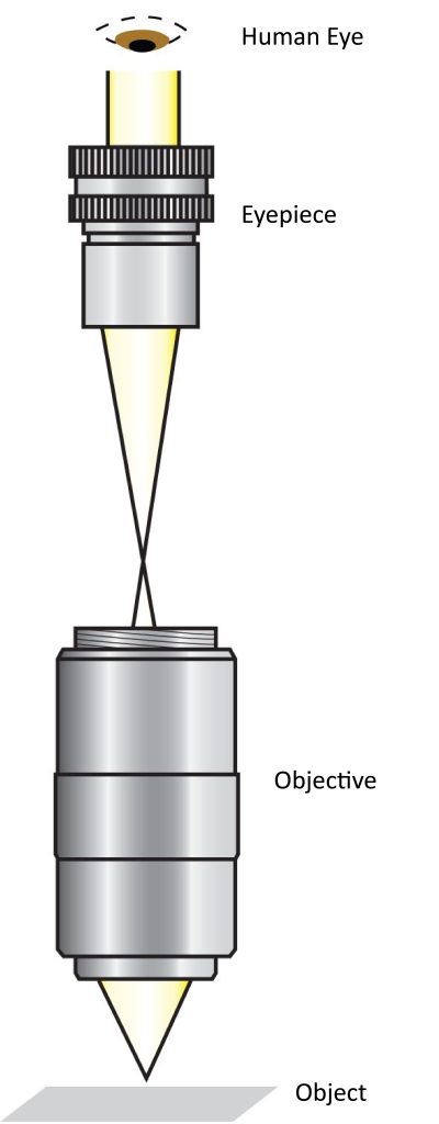
In infinite conjugate (also called far-field corrected) optical designs, a light source located at infinity is concentrated on a small point. This small spot is the object under observation in the objective lens and is at infinity facing the eyepiece or camera’s sensor (Figure 12). This novel microscope mainly uses an additional tube lens between the object and the eyepiece to produce the image. Although the structure of this microscope is more complex than a finite conjugate objective, it allows the user to incorporate optical components such as filters, polarizers, and beam splitters into the microscope. Therefore, additional imaging analysis and extrapolation can be performed in this complexly designed microscope. For example, adding a filter between the objective and tube lens allows the user to observe specific wavelengths of a light source, or blocks unwanted wavelengths that interfere with the microscope setup. Fluorescence microscopy applications utilize this type of design. Another advantage of the infinite conjugate design is its ability to vary magnification based on specific application needs. Objective magnification is the ratio between the focal length of the tube lens and the focal length of the objective lens (Equation 5). Increasing or shortening the focal length of the tube lens will change the magnification of the objective lens. Typically, tube lenses are achromatic lenses with a focal length of 200mm, but lenses of other focal lengths can also be used to help customize the overall magnification of the microscope system. If the objective used is a wireless conjugate objective, the infinity symbol will appear on the objective body.

5. Optical microscopy application examples
To understand how microscope components can be integrated with a variety of optical, imaging, and optoelectronic products, consider the following optical microscopy applications: Fluorescence Microscopy Applications and Laser Ablation Applications. Each application has a unique setup that works with the components of the microscope.
Fluorescence microscope
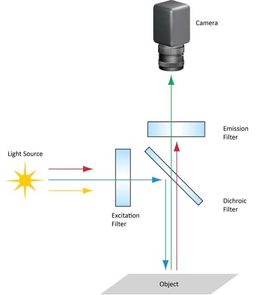
Fluorophores are fluorescent stains used to add fluorescent labels to proteins, tissues, and cells for detection or research. Fluorophores absorb light of one wavelength and then emit (fluoresce) light of another wavelength. A typical fluorescence microscope setup uses three types of filters: excitation filters, emission filters, and dichroic filters. Each fluorophore has a specific absorption band wavelength or excitation band wavelength, and the excitation filter only transmits a specific range of wavelengths. Once excited, a fluorophore emits a different range of wavelengths. Emission filters can only be used to transmit the emission wavelength. Dichroic filters are designed to reflect emission wavelengths and transmit excitation wavelengths, and serve to separate the excitation and emission channels. Figure 13 shows a typical fluorescence imaging setup.
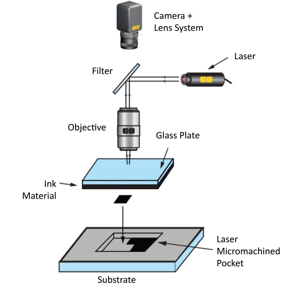
Laser ablation applications
Two common uses for lasers are: (1) to heat and plate material onto a substrate, and (2) to ablate substrate material to remove it. The reason why laser ablation systems use microscope components is that they require precise laser beam manipulation (such as focusing, refraction, scatter attenuation, etc.). Laser ablation setups often opt for custom optics rather than off-the-shelf optics, and lasers are carefully designed for the system (Figure 14). The positioning of the laser in the epi-illumination design takes full advantage of the ability of the microscope objective to focus light on the object plane, resulting in a smaller spot size and reduced aberrations. In addition, users can observe the position of the laser through the eyepiece and ensure that the system is operating properly. In laser ablation systems, the use of optical filters is necessary as this protects the user’s eyes from laser damage. Laser ablation settings are commonly used in medical and biological applications because they provide greater precision than traditional surgical methods.
Microscopes and objectives are complex optical systems with many uses. Their use is no longer limited to biological applications (such as observing buccal epithelial cells in a biology class). Instead, users can use these optics to observe emission wavelengths in fluorophores and analyze 5 μm defects in processed lenses. , supervise the ablation process of substrate material removal, and use with various optical, imaging, and optoelectronic products. A thorough understanding of the importance of each component of a microscope and its specifications can help users choose the most appropriate microscope system to obtain the best results in their experiments.